iPad app a go
Well, WordPress keeps getting better, I’m now using the iPad app. This makes updating the posts a real breeze.
Hopefully this will mean more updates in the future!
Project Bad Apple
Project Summary:
Some of my favourite case designs have come from Apple and I have always wanted to convert one of their cases for PC use. I finally got the chance with this project to do just that. This project has featured in both Custom PC magazine and on Hexus.net
Project Bad Apple: Full Project Log
2003-09-01
Apple computers have for a long time now led the world in design. They were the first mainstream manufacturer to make a pc look any good. They rewrote the rules for the beige box. To get a pc that looks as good as a Mac is quite hard even nowadays. I’ve long been a fan of the G4 case and was determined to get hold of one for a project. After almost 2 years I finally got my wish. This article will describe the route I took to complete the project I named ‘Project Bad Apple’.
A Quick Note or Two.
This project guide is going to be slightly different to the normal project log: it is going to be very text heavy. A picture speaks a 1000 words and its much easier for you to get the idea of what I’ve done with them. I took well over 300 images during the build I have used the best ones. I’ve tried to explain how I did everything in the most obvious order not in the order that I did it so if I get confused about the time sorry.
If you intend to copy or repeat any of the mods described in this article please be aware some of them have inherant risks and should only be undertaken if you know what you are doing.
Please note I take no responsiblity for any damage to parts of persons as a result of this article, sorry we have to cover our backs nowadays.(Mumbles something about lawyers).
Aims of the Project
I’ve been wanting to do a G4 to ATX case conversion for ages now, I really wanted to get a quicksilver case but they are a lot harder to come across. So I settled for a stock G4 case I bought from the US via Ebay. My aim for the conversion was that from the outside there was very little to differentiate it from a Apple G4. This means as
The Apple Mac G4 Case
The stock G4 case is around the size of a MATX motherboard, with some main differences. The motherboard ports do not line up with the ATX I/O plate at the rear of the case and the Motherboard standoffs don’t line up either. In order to convert the case both these issues would haven to be addressed. The case itself is made of stainless steel with perspex panels to give the case its great looks. All of these panels can be removed very easily with a few clips and bolts. To access the inside of the case, there is a small lever and the whole right hand side of the case drops down with the motherboard in place. This gives excellent access to the motherboard, the lever can be prevented from opening for security reasons if neccessary by using the inbuilt padlock loop at the rear of the case. A great addition for LAN parties.
Here is the case fresh out of the box, it looks great.
Next I opened up the case and look at what I was going to be modding. I then removed all the plastic parts from the case to get it down to its bare shell.
The bare shell from the front and two parts that need to be removed. The first is the wireless network aerial, and the second is the support for extra long pci cards and the slot for the wireless network card. Also on this is a small magnet which prevents someone opening the case while its powered on. I will take these off later.
Power Supply
The first part I wanted to fit was the Power Supply(PSU). In the stock Apple setup the PSU is similiar to a ATX sized one from a normal PC case. I didn’t need or want a PSU this large so I choose a smaller MATX sized one I had lying around from an earlier project. I decided to spray paint it a nice shade of metallic blue. I used normal car paint with a layer of primer then the colour coat and finally a clear coat to give a nice shine. The PSU fan is a 80mm sized fan but its thinner than a normal 80mm fan. Luckily the fans I choose (Coolermaster LED fan) fitted. The fan was modified as described later in this guide in the fans section.
In order to attach the PSU to the case I need some kind of adapter, I had some spare perspex lying about and got out my Dremel and cut out a peice that would fit perfectly. The holes were then measured and drilled out so that it could be attached with normal pc type screws.
Fans
I am a real difficult person when it comes to fan choice, I want really quiet fans that look nice and can be controlled easily. I’ve not yet found my ideal fan but the best comprimise solution I’ve come across is the Coolermaster LED fans, they are clear fans with 4 LED’s for lighting (RED. BLUE , GREEN , WHITE or PURPLE in colour). The fan is quite quiet at stock speeds and can be modified to make them quieter. They are more importantly very cheap in comparison to the normal quiet fan options. I sourced four 80mm white versions for this project. One for the CPU Fan, one for the PSU, and two for the case cooling.
Fan Modification
In order to control the fans noise levels I wanted to be able to control the speed of the fans. This means adjusting the voltage supplied to the fans. Now in a normal fan this is easy, in LED fans things get slightly more complex. The LED’s in these fans are fed by the same power as the fan themselves, this means that when you lower the voltage supplied the LED’s get dimmer. Clearly this wouldn’t do, so I set about modifying the fan so that this wouldn’t happen.
The parts/tools I needed for this were:
- Soldering Iron/Solder
- Heatshrink
- 1 x Resistor per fan (120Ohm)
- Some wire
- Wire Cutters
- A lighter
The first step I took was to peel back the sticker that hides the wires in the center of the back of the fan. I held it back with a small section of bluetac.
The LED circuit is powered via three clear wires, so I unsoldered them from the fan keeping the two that were soldered on the same connection together (Positive wires). While I was at it I unsoldered the yellow wire as this won’t be used in the connector I am using.
Now I soldered the Resistor to the two power wires I had unsoldered before. After which I added a length of wire after the resistor and solder it into place. When I’d done this add some heatshrink over the bare wires and used the lighter to shrink it into place.
Now solder a length of wire onto the negative LED wire and heatshrink the bare cable. Once this is done you are free to use the connector of your choice. I’ve used a four pin connector similar to the standard three pin one. With the 2 fan leads and 2 LED leads connected.
Fan Control
To allow me to control the speed of the fans from one single point I devised a circuit that would allow me to power the fans from a single point. Its to be made of stripboard as its only a basic circuit.
The parts/tools I needed for this were:
- Soldering Iron/Solder
- 4 x 4 Pin female connectors
- 2 x 3 Pin female connectors
- Some wire
- Wire Cutters
- Rheostat fan controller.
The first step is to solder the four 4 pin connectors to the section of stripboard making sure there is space between them and that the copper tracks are connecting them together. Parallel to the 4 pin connectors solder in the two 3 pin connectors again space them a couple of holes apart. Once these are done you can add the wires , you need two wires powering two of the four pin connectors tracks. The other two that take the power from the top of the three pin connectors to the other 2 spare tracks on the 4 pin ones. After this add a positive and negative pair of wires that connect to a molex connector.
The basic circuit is now done, I have a rheostat which has 3 pin input and output which slots into the three pin connectors. This rheostat is mounted in a spare pci slot as its a convenient way of hiding the switch but it still being accessible.
I tested the circuit out on my shuttle machine and it worked perfectly. I then mounted the circuit using sticky velcro tabs onto the side of the PSU. All the fans in the system are hooked up to this circuit so one turn of the knob controls all of the fans.
Removing Unwanted Case Parts
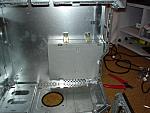
Lining the motherboard up for a test made me quickly realise there was going to be a major problem. The motherboard wouldn’t fit. The memory slots were hitting the section of the case where the cd drive was due to go. This was going to be a major pain in the backside. My first idea was to remove the central case strut and cd drive sections from the case, and run the Optical drive in an external case either USB 2.0 or firewire. With this decided I got out a drill and removed the rivets holding the central strut in place.
As you can see, in the picture above when I shut the side of the case, the memory slots hit the side of the cd bay; this would have to be fixed.
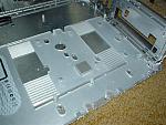
Then I removed the extended PCI card holder and wireless network slot again held in with rivets. This gave me a much larger space to work with. While I was at it I removed the aerial for the wireless network which is attached to the side of the case with small screws.
Modding the Motherboard
Lining up the motherboard for the first time showed another problem, the audio ports where not going to fit. These were too low on the standard ATX I/O plate and would hit the back of the case preventing the motherboard from being placed in the right place. The solution is to remove them from the motherboard entirely, which means attacking it with a soldering iron and wire cutters. Its not an easy job and you are very likely to kill the motherboard if you are not carefull.
The motherboard I am using is a Gigabyte GA-8IG1000MK, its a Intel 865G MATX board. The board is the best specified Pentium 4 MATX board I can find at the moment with onboard audio/network/graphics and other goodies such as SATA. I really liked this board.
While I was removing the audio connector, I decided to remove the parallel port as well as I never use them. Next I attacked the audio port, the minor side effect being blood pouring out of my finger. This modding lark hurts more than they give credit sometimes.
Mounting the motherboard
In order to fit the motherboard I was going to have to do a lot of work. I needed to cut off the old motherboard standoff’s and fit new ones.
Here the dremel fun begins, I have to cut off all the old motherboard standoffs with the dremel. Lots of sparks and dust later I had removed them all.
In order to get the motherboard in place I needed to cut the rear ATX I/O plate a bit, again I attacked it with a dremel.
For the motherboard standoffs I used small 1cm hexagonal spacers. I had to drill the holes and make sure the plastic (Part of the door opening mechanism) was able to move as before. I finally got the motherboard in place. The project was starting to take shape.
Cooling
I wanting to find a great looking cooler for this project. It needed to support 80mm fans and be an excellent cooler. The obvious choice was the Swiftech MCX 4000. Overclock.co.uk, kindly provided the cooler along with a few grills and a filter for the bottom blowhole. Its nice to get some support from stores like Overclock.co.uk and its greatly appreciated.
The swiftech cooler along with the grills and filter. Mounting the cooler onto the motherboard requires the stock P4 mounting to be removed. Then the cooler is bolted into place. It looks great with the 80mm clear fan.
In terms of physical cooling the Swiftech is excellent. It is better than any other cooler I’ve used before. The temperatures with the fan on really low voltages is amazing.
CD Drive
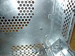
I originally planned to use the normal layout of the standard Apple Mac G4 with the optical drive but this was not going to be possible. The next idea was to use an external drive bay but they are expensive and it wasn’t an ideal solution. However while looking at the case I realised that it would be possible to mount the drive on its side ejecting out of the back of the case. This would mean that I would need to remove the 120mm fan and its shroud but this wasn’t a problem.
First I need to remove the screw mounts for the 120mm fan, I attacked them with a dremmel and cut them off.
I intended to mount the drive using 2 brass brackets, after drilling the mounting points I realised I hadn’t taken into account the perspex handles at the drive wasnt able to eject. Luckily I hadn’t cut out the slot yet so I re-did the mounting with the drive raised higher.
With the drive placement fixed, I cut a thin slot in the metal at the rear. The CD is ejected via Windows or pressing the button which is accessible through one of the old vent holes.
The slot being cut out of the perspex and the CD drive tray ejecting from the rear of the case.
Blowholes
I had always wanted to add a fan to the bottom of the case, but with the 120mm case fan having to go I decided to stick a 80mm blowhole at the top of the case as well.
To make the bottom blowhole I cut out the hole with my trusty dremel. With the hole cut and filed back to shape. The bolt holes were drilled out as well.
In order to prevent dust being sucked up into the case I fitted a filter to the bottom fan.
With the top fan I repeat the same dremel process as before to create the blowhole in the steel chassis.
This time I added some blowhole trim as it is going to be on show. I then had to cut the perspex section as well to get air out of the case.
The perspex was again cut with a dremel then filed back to shape with a sander. With the white LED fans the top blowhole looks ace.
Extending the PSU Cables
Due to the way that the case opens I needed to make an extra long PSU cable, I sourced a male and a female atx connector and set to work soldering all the wires required. Its long and boring work but it was cheaper than buying one. I wrapped the finished cable in black tape to make it look at lot nice. I also extended the p4 connector to reach the motherboard.
Switch Gear
I wanted to use the existing switches to keep the case looking as standard as possible. The existing switch circuit is setup for the mac and requires alteration for pc use. I tried to convert it but it wasnt very succesful so I ditched the circuit and bought some cheap push to make switches. And set about making an aluminium plate to hold them in place.
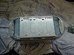
Here is the stock circuit, its mounted inside a steel square which clips into place. On the back there was a reed switch which disables the power buttons when the case side is opened. I bypassed the reed switch entirely and tried some modification of the orginal ciruit but it didn’t work.
Here’s the alternate switch setup, I made a sqaure of aluminium and drilled the holes for the two switches and the LED.
Finshing touches
With all the modding done it was time to put everything into the case and boot it up for the first time. It worked fine with the side down, booting first time. However, when I closed the case the system shut itself down straight away. I quickly found that the motherboard was shorting out on the square of metal keeping the plastic section used to open and close the case in place. I used some tape to insulate the piece of metal and it was all sorted. I took the perspex panels off and gave them a good scrub down in the bath and then removed the fine scratches with Novus polish.
I use the system as my day to day system, using it for games and work. I love the case, it looks great and is fairly easy to cart around.
Gallery
Here are the final selection of pictures.
Work in Progress
Obviously there is still a lot of work to do on the site. I am however beginning to make progress.
This is my first play with wordpress and so far I’ve been very impressed. It’s very easy to work with and template tweaks seem to be a breeze.
The next big step is to start importing the old content across. This is going to take lots of time so it won’t be done in the next couple of days.
I will start with the popular articles and then work back from that.
Welcome
Hi
After years of neglect, it’s time for me to spend some time updating the site. Bare with me whilst it happens.
Thanks


