Blog

  • Z650 Update and Rewire

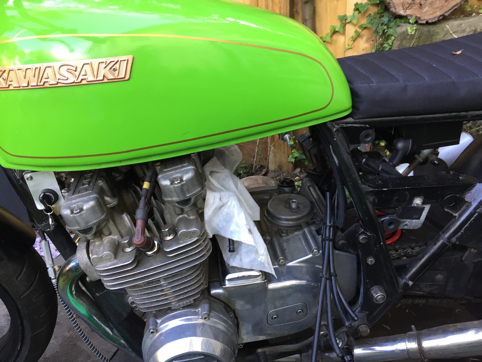
    So it was about time I updated this project log. I’ve ridden the bike a few times, but I’ve been suffering constant electrical gremlins. I tried replacing the regulator with a Shindengen SH775 ,but that didn’t fix things.  As the weather has been foul I’ve not had a chance to do much work on the bike.

    For some time now I’ve wanted to do a complete rewire so finally I said sod it and got started. First off I wanted to do it properly and easily so my first purchase was a Motogadget M-Unit

    Motogadget M-Unit
    Motogadget M-Unit
    Motogadget M-Unit
    Motogadget M-Unit

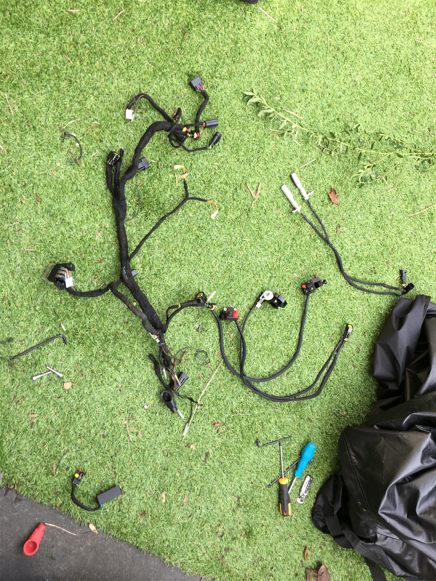
    It’s an amazing bit of kit, it makes life much easier for the rewire. To go with it I’ve order lots more kit that is arriving shortly I hope. In the mean time I started removing the old crap wiring.

    IMG_8779

    The bike looks much cleaner with out all that rubbish hehe

    IMG_8780

    When the rest of the kit arrives I can start planning the next phase. Here’s some of my shopping list:

    Dyna S complete coils/ignition kit
    Motogadget M-Unit
    Motogadget M-Lock
    Shorai Lithium Battery
    New Spark plugs
    Loads of wiring bits.
    Uni Clamp On Air filters
    Starter Relay

  • Nerf Stryfe Tacticool Extreme

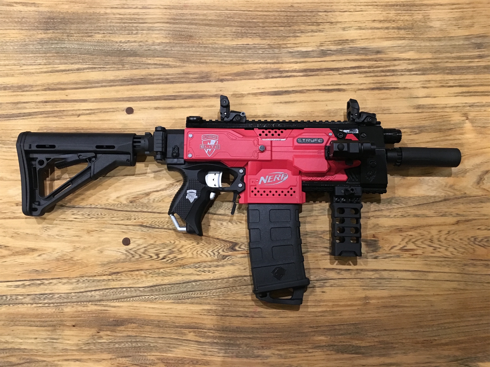
    So since I last updated the blog, I’ve made a ton of changes and progress on the stryfe.  When I first planned it out I wasn’t intending to do any painting or majors changes.  It was going to be a 3d printed Kriss Vector replica.  However I wasn’t a fan of the final look as it looked rather bulky and orange.  So I decided to make some changes to the plan.

    1. Only use some of the kriss vector kit, ditching the mag cover and stock.
    2. Paint the main blaster red with a black grip.
    3. Remove the IMR based setup and replace it with a proper lipo setup.
    4. Get more tacticool bits, because clearly it needed more.

    Step 1 was to order a ton of bits from Taobao as they take a long time to arrive.  I then ordered some battery bits and bobs from Hobbyking.

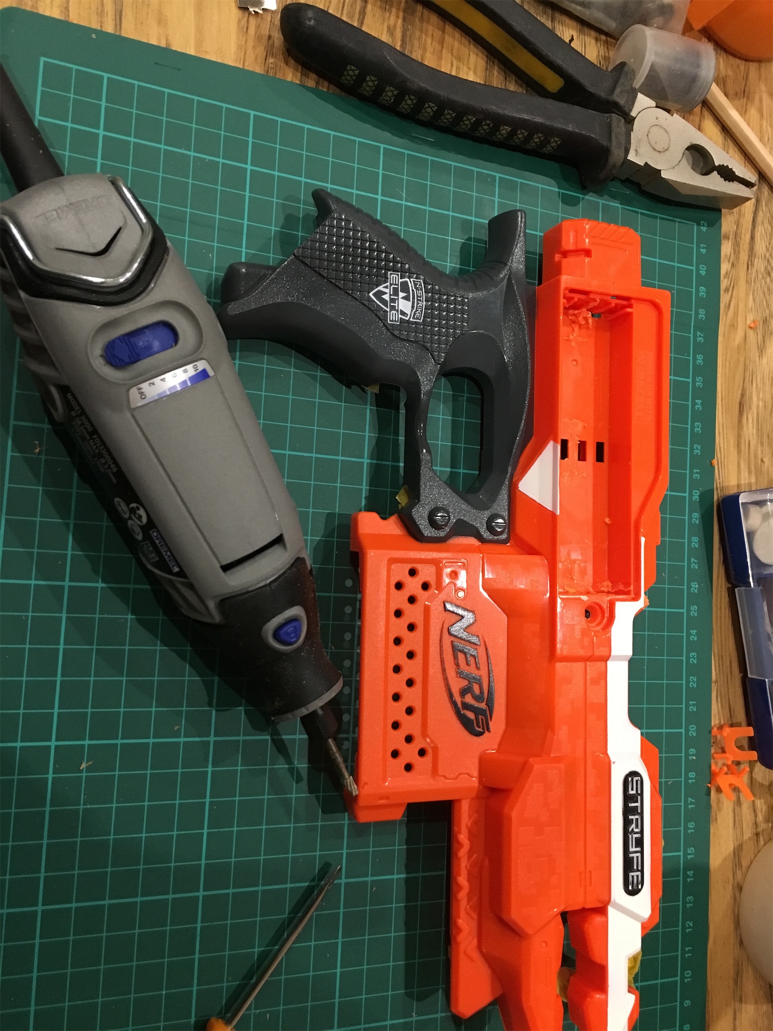
    Step 2 was to start attacking the battery tray with my dremel to free up room for the new battery.

    IMG_8653

    IMG_8651

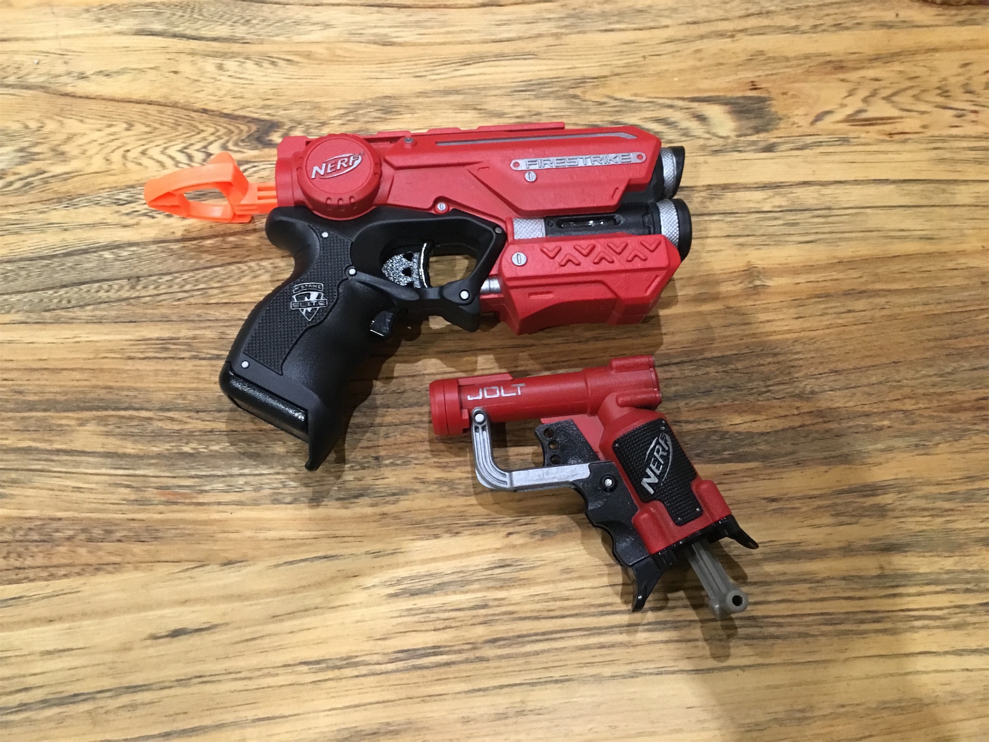
    Step 3 was to get painting.  As I had practiced on some firestrikes and a jolt I was confident in how I was going to get it done to my satisfaction.

    IMG_8631

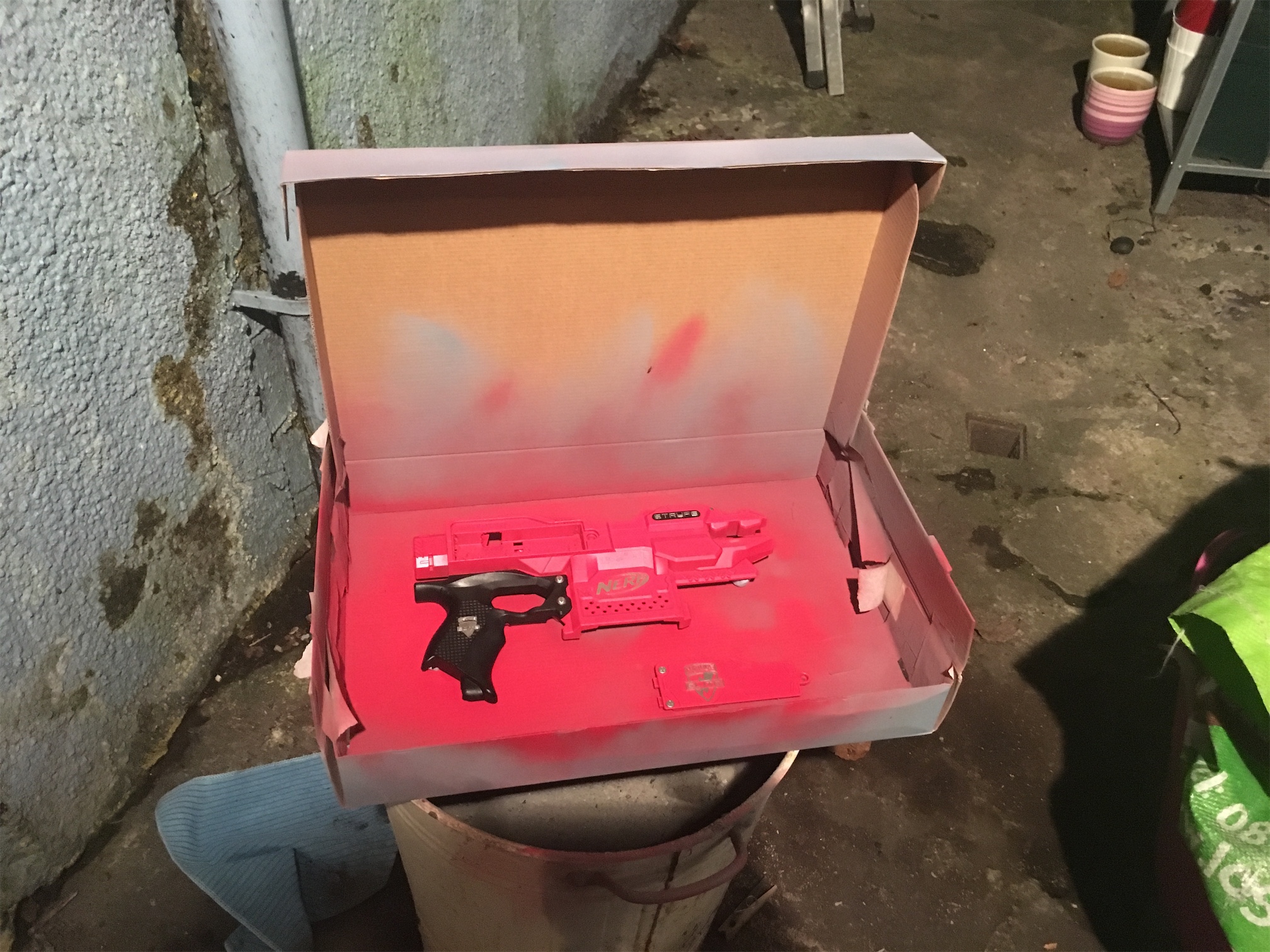
    I used a lot of really light coats to build up the layers of paint slowly.  Spraying too much in one go results in losing detail and a bad end result.  I use a box to contain the parts and paint as much as possible.

    IMG_8654

    IMG_8656

    IMG_8708

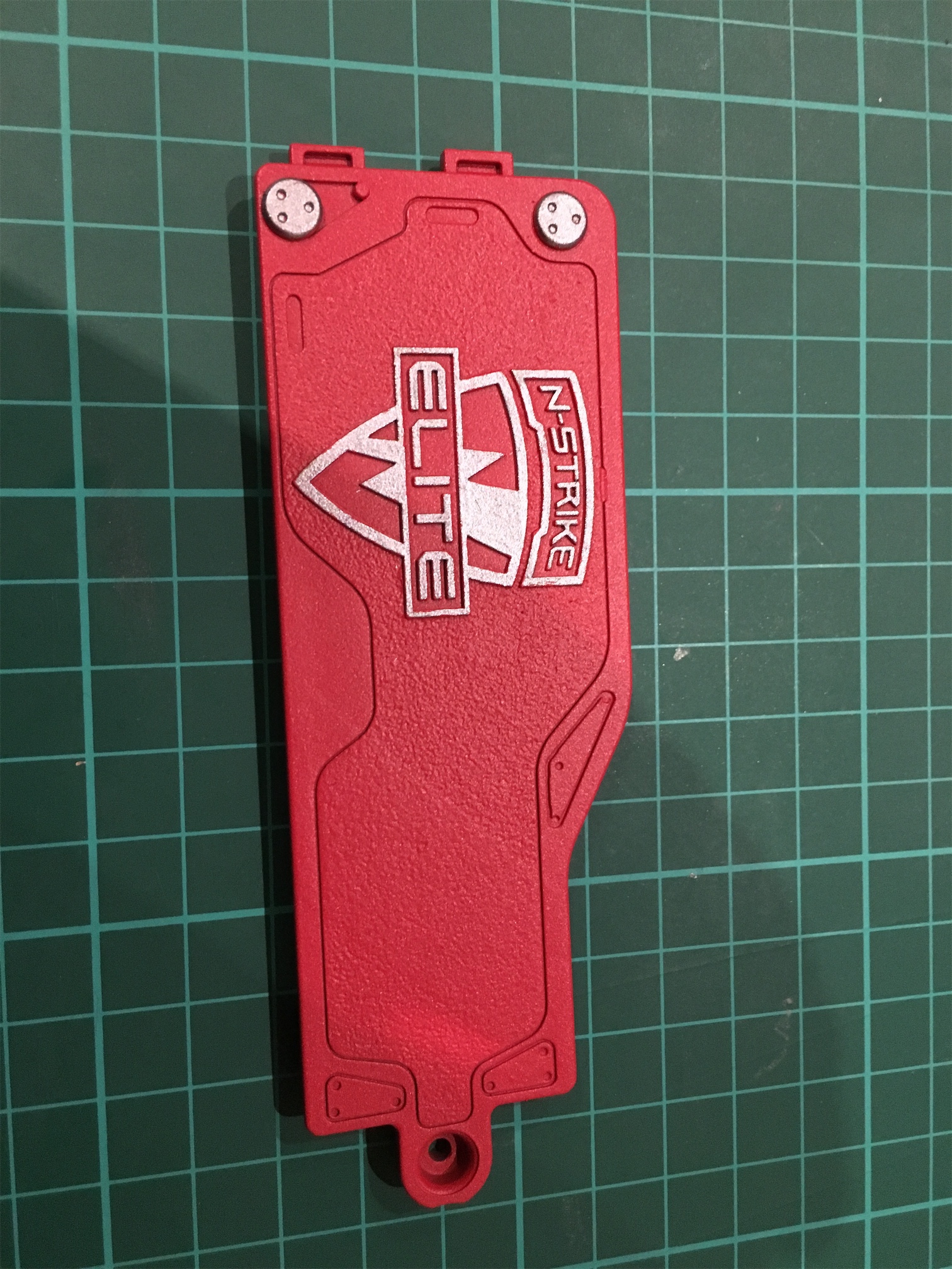
    After the final coats of Plastikote Matt Red, I then set to work detailing it with enamel paints and a brush.  I was very happy with how it turned out.

    IMG_8687

    IMG_8684

    For the triggers and other parts I went for a silver finish as a contrast.  I’m very pleased with how it turned out.  I left the bits that won’t be visible as orange for speed.  It also allows me to make it much more toy looking if I ever want to use it more publicly.

    IMG_8726

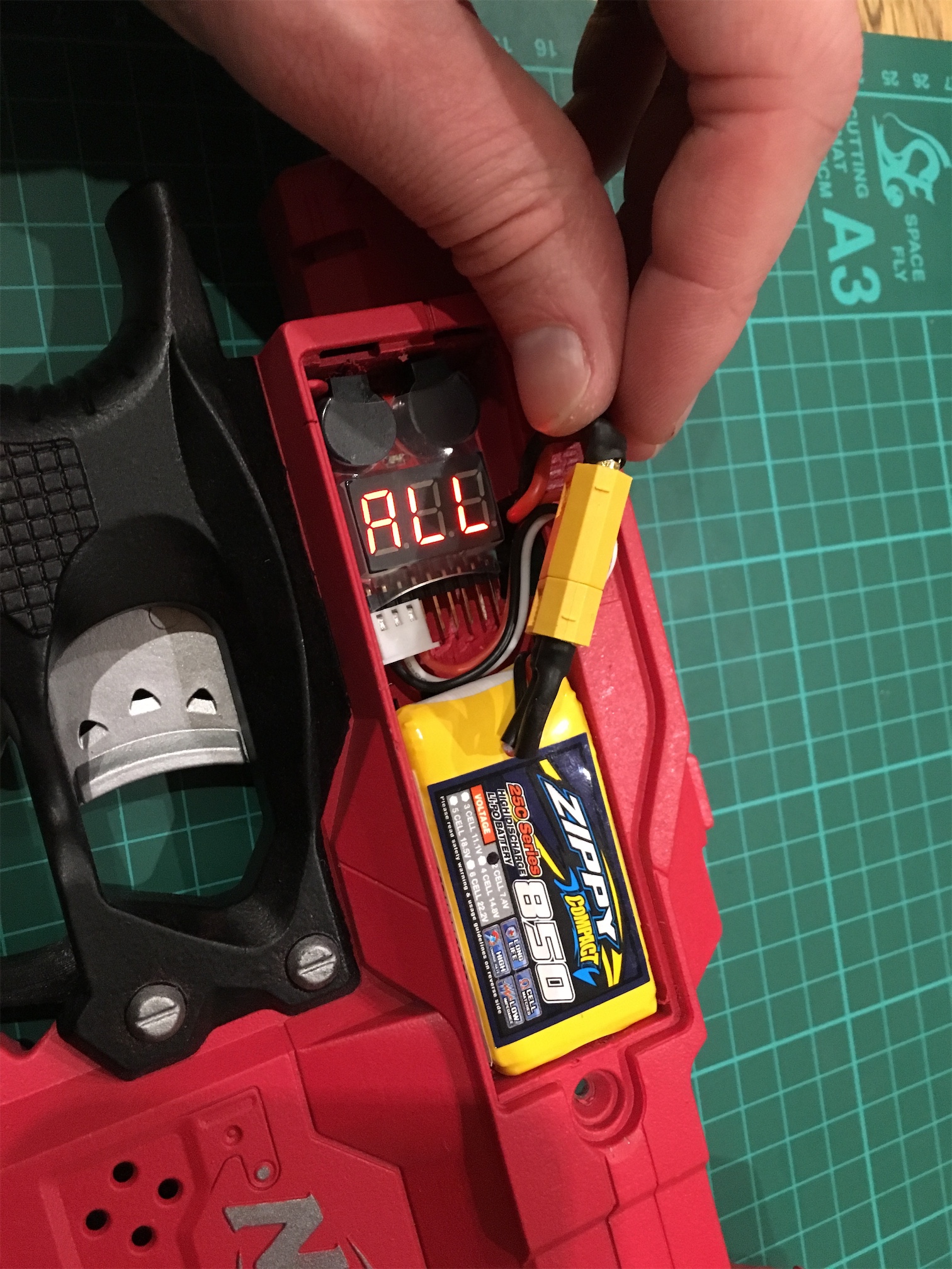
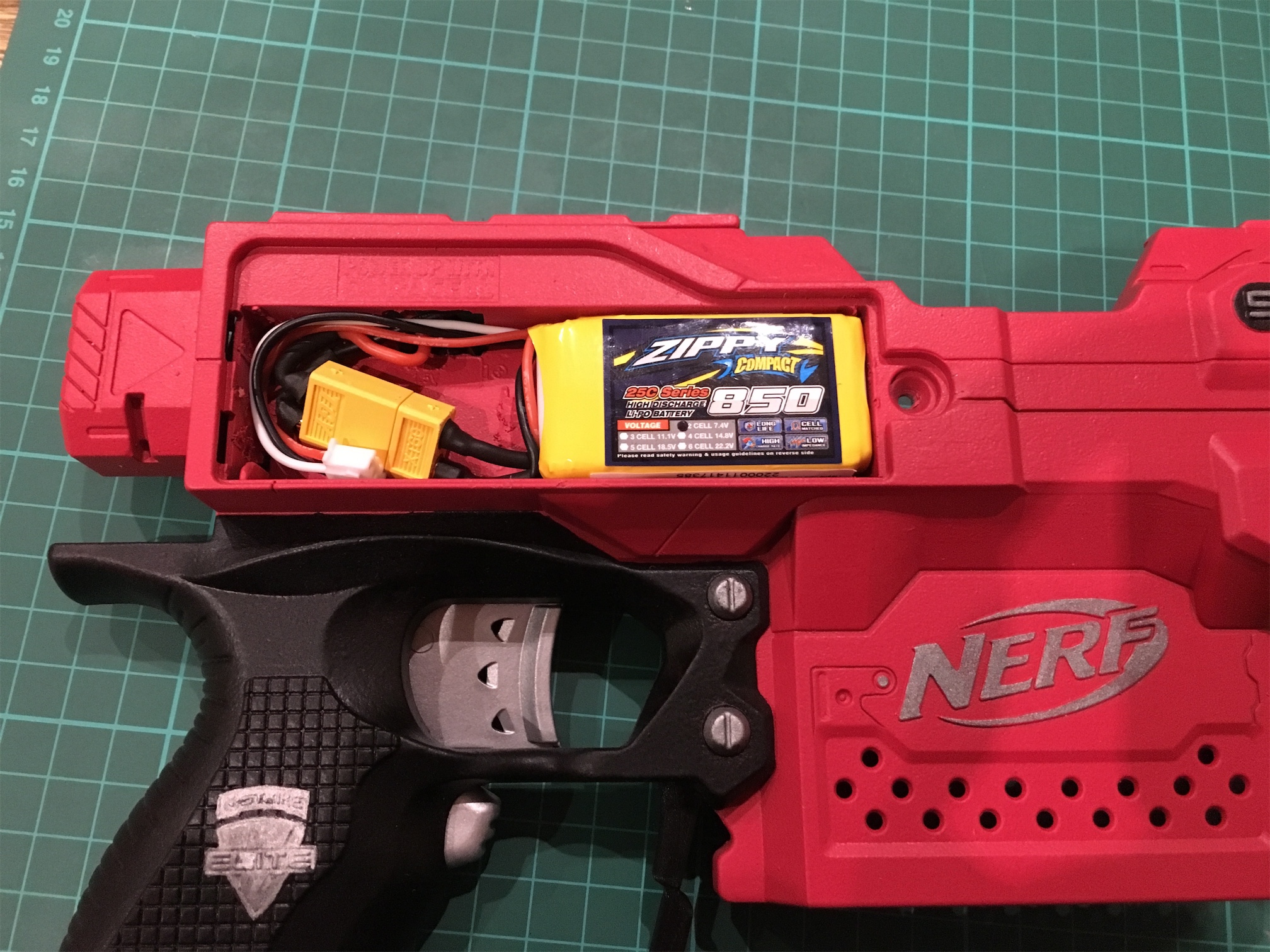
    Next up I had to wire in the new Lipo system.  I went with an combination alarm and digital display, but at present it’s not fitting in place.  I will have to come up with a solution to this soon.

    IMG_8735

    IMG_8734

    IMG_8733

    The battery cover just fits in place with the battery in and the plastic ridges dremel’d off the battery cover.

    By now my Taobao order had arrived with some new goodies.

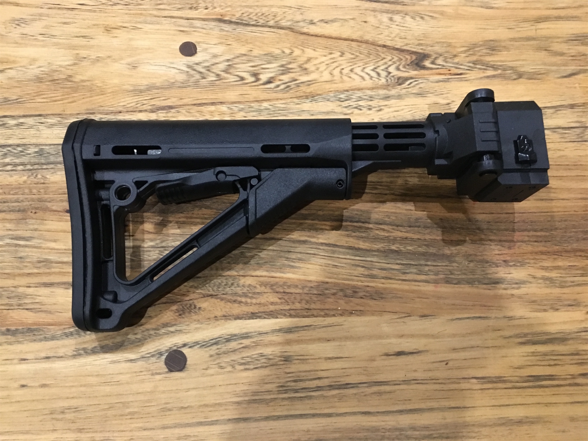
    1. Folding Worker stock mount and CTR adjustable stockIMG_8716
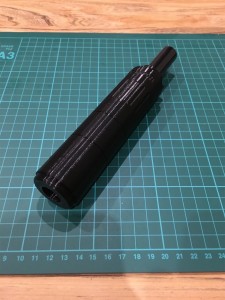
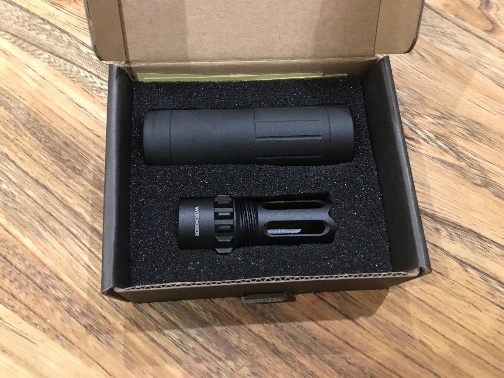
    2. Worker aluminium silencer and flasherIMG_8718

      IMG_8719
    3. Worker 12 round Mag’s with pullerIMG_8717
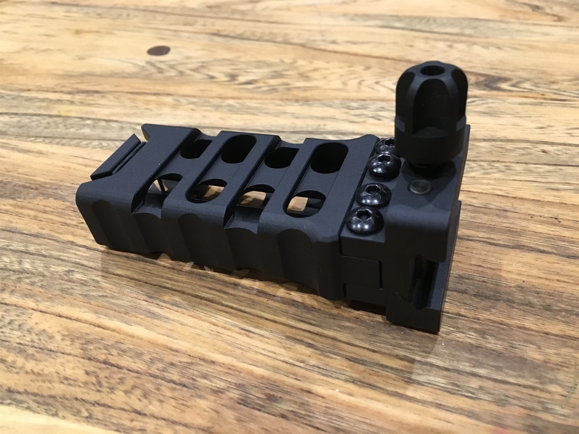
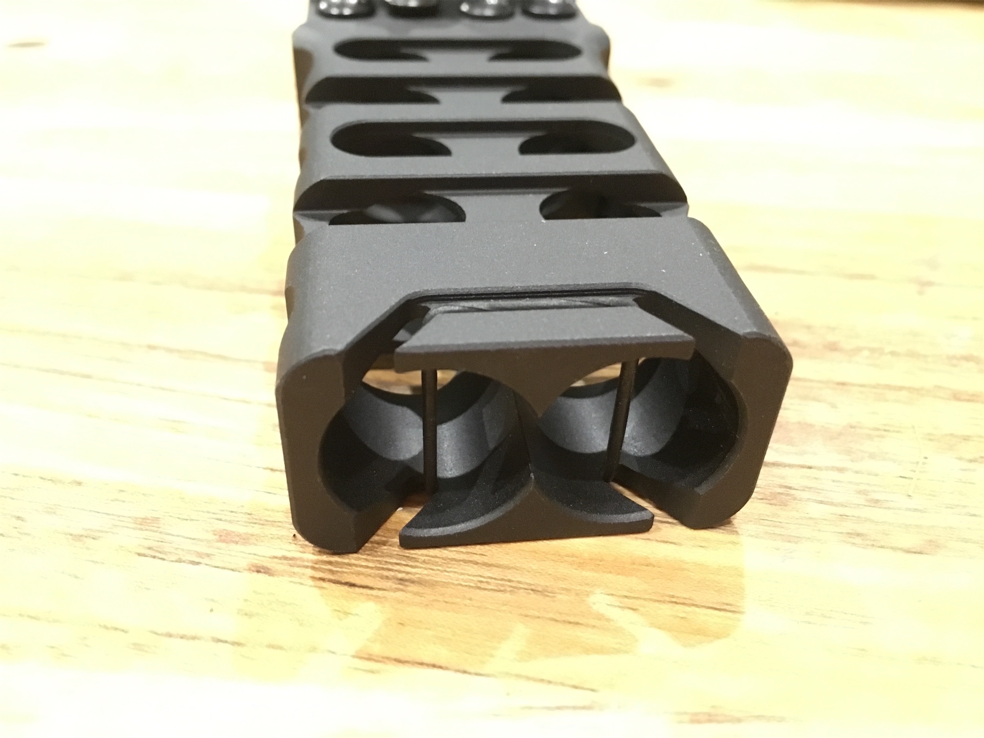
    4. Finally a little something special. A new aluminium foregrip.  It’s a stunning bit of kit and I love it.  It even has a space inside for spare batteries.IMG_8725
      IMG_8724
      IMG_8723
      IMG_8722
    5. I had some other trinkets in the order such as MBUS sites and a sling.  Along with parts for my rapidstrike and demolisher builds.

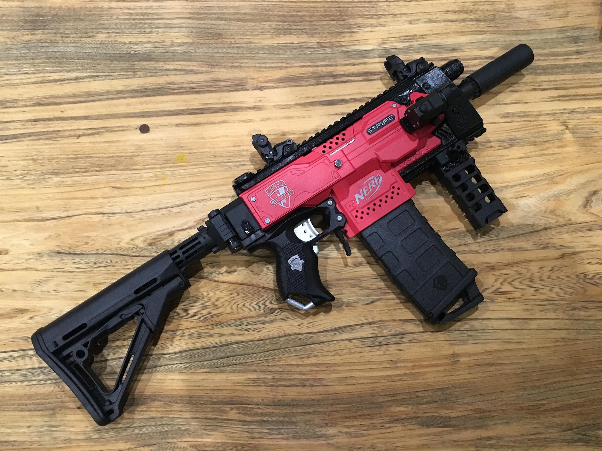
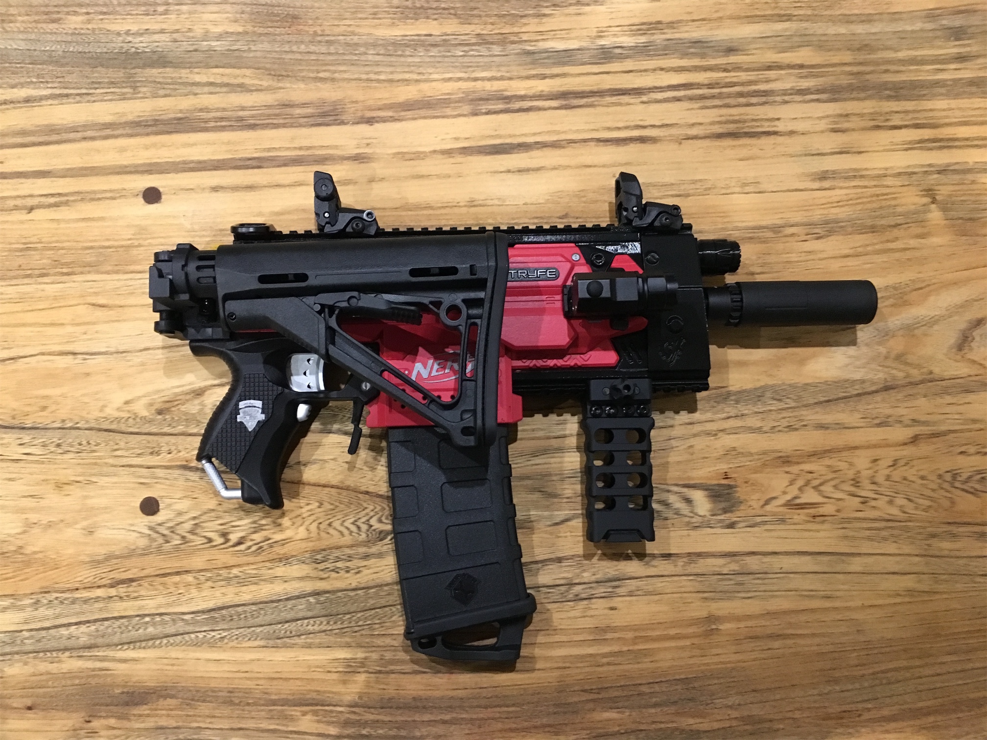
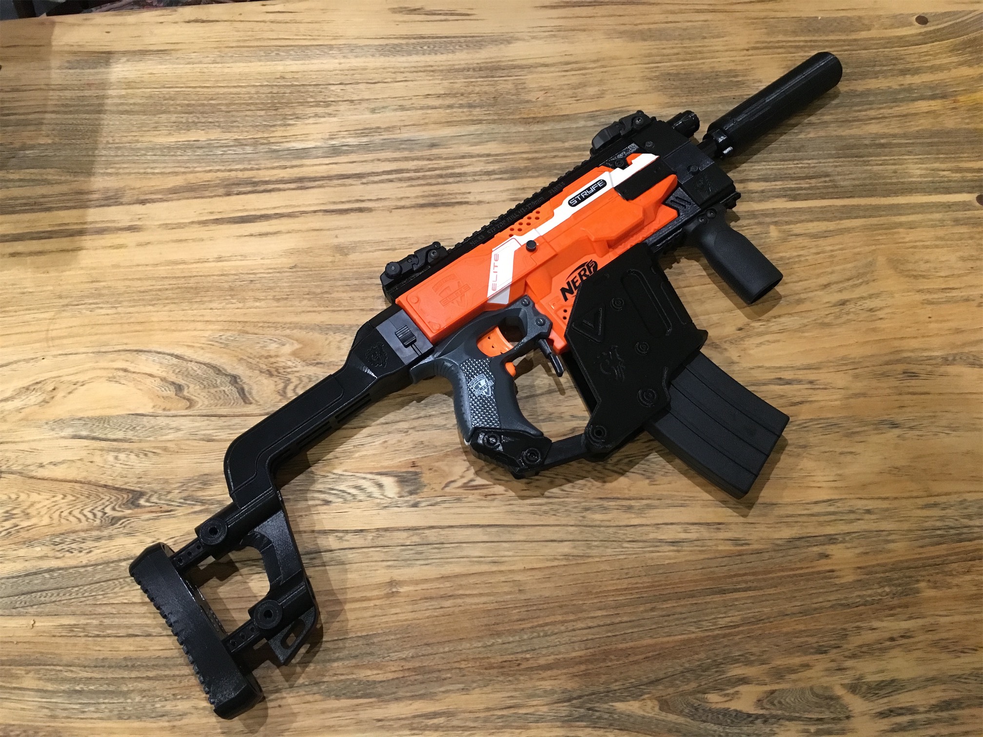
    I could now set to work assembling the blaster, I was exceedingly happy with the end result.  It has some serious weight to it now!

    Nerf Stryfe Tacticool
    Nerf Stryfe Tacticool
    Nerf Stryfe Tacticool Folded Stock
    Nerf Stryfe Tacticool Folded Stock
    Nerf Stryfe Tacticool No Stock
    Nerf Stryfe Tacticool No Stock
    Nerf Stryfe Tacticool with Stock
    Nerf Stryfe Tacticool with Stock


    It looks very different to how it last looked.

    Nerf Stryfe Kriss Vector
    Nerf Stryfe Kriss Vector

    Here is a video of it in action

    The final spec’s/parts are as follows:

    Nerf Stryfe
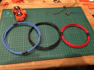
    18 AWG Rewire
    2 x Rhino MTB Motors
    2S Zippy Compact 850 battery
    XT60 Connectors
    Worker Flywheels
    All locks removed
    Gavinfuzzy 3d Printed Mag release.
    Worker Aluminium flasher and silencer.
    Worker 12 Pmag with puller.
    Worker battery thumbscrew
    Worker folding stock
    CTR Stock
    MBUS sights
    F10555 3D Printed top rail
    F10555 3D Printed side rail
    F10555 3D Printed bottom rail
    F10555 3D Kriss Vector front section
    Viking Tactics Ultralight Vertical Grip
    TrustFire LED Gun Tactical Flashlight

    I hope you like the end result as much as me.

  • Nerf Stryfe Worker Flywheels and Wall hanging

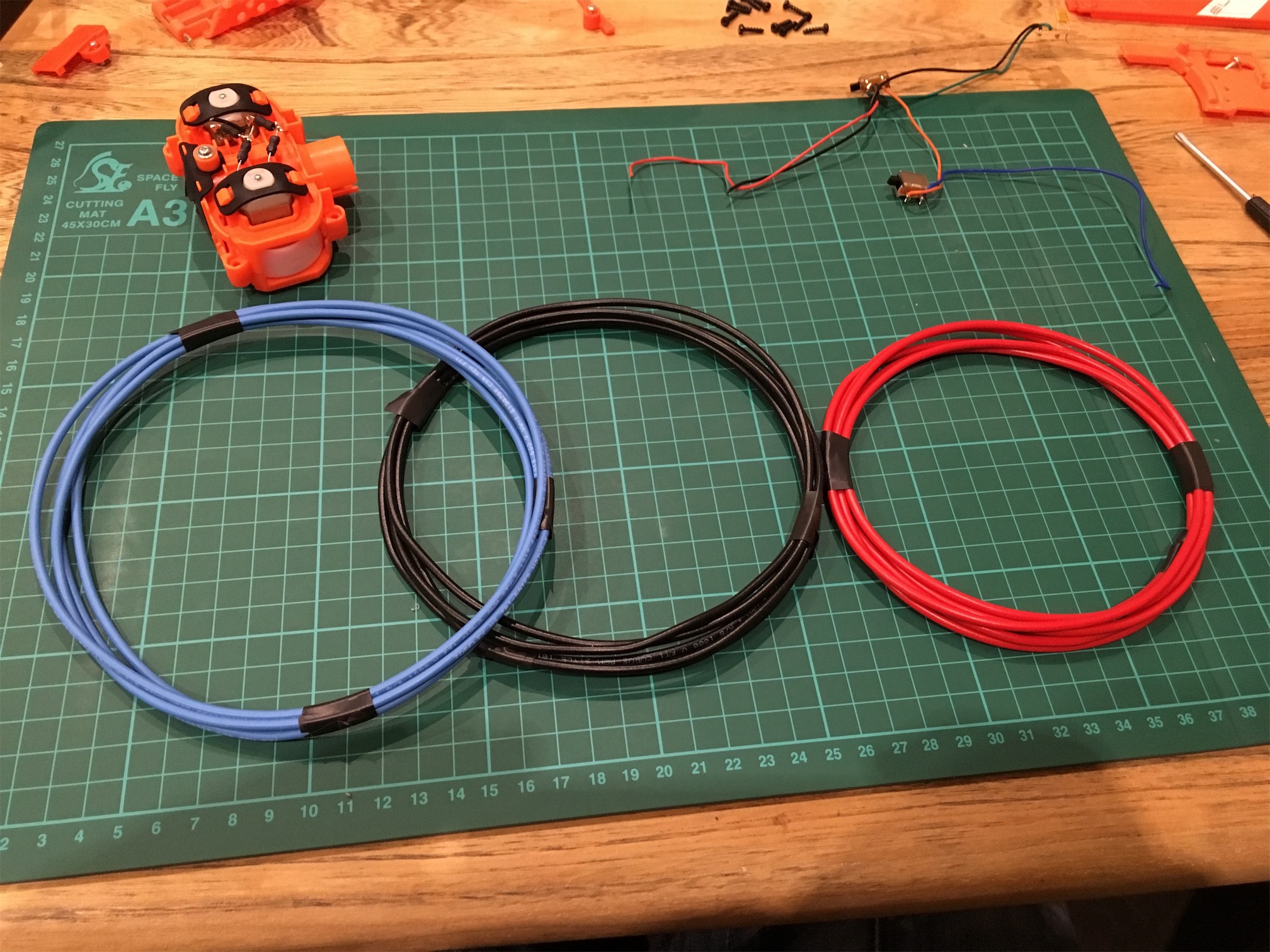
    So I had a bit of a wait for more parts to arrive.  The main ones were the rhino motors and worker flywheels.  Once they were here I could take the Stryfe apart again and this time wire it properly.  The silicon wire was so much easier to run round the blaster.

    IMG_8390

    I got the rhino motors wired in and the worker flywheels fitted.

    IMG_8392

    After that I needed to find a way of wall mounting this blaster for storage in my office.  I looked around at lots of hooks and off the shelf items, but none were suitable.  In the end I decided to make my own.  Five minutes with a bending brake and saw and I had these:

    IMG_8384

    I laid foam on the inside of them and fitted to the wall via screws.  The blaster looks awesome up on my wall.

    IMG_8381

    IMG_8380

    Once I’d completed this blaster I set to work on my kids one making some changes/improvements.  I ended up with this result that they are delighted with.

    IMG_8415

    I’ve got one more part arriving for my Stryfe that will see it completed.  Next up I want to finish my Demolisher internal mods before starting on some Nerf painting projects.


  • Nerf Stryfe Mods

    Whilst it’s cold wet and miserable out there, it’s been hard to get any work done on the motorbike. I’ve instead taken to modding Nerf guns.

    I picked up a Nerf Stryfe after xmas as it seemed to be a great blaster for modding.  There are so many choices for things to do to them and lots.  It started with this post on reddit: Merry Kriss-mas. It’s the Kriss vector kit for the Stryfe.  It looked awesome.  I discovered the joy/pain of Taobao and trying to purchase items from there.

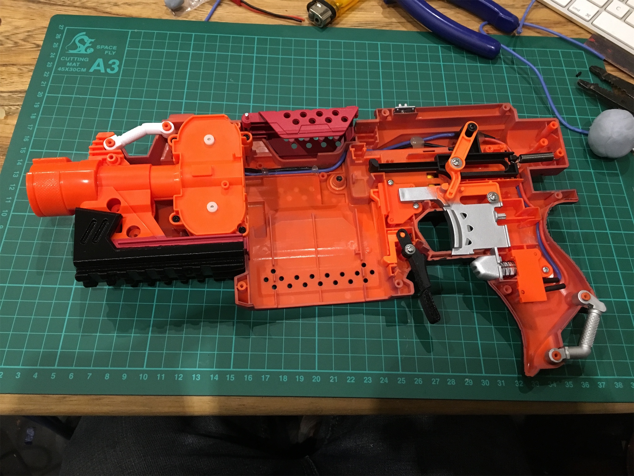
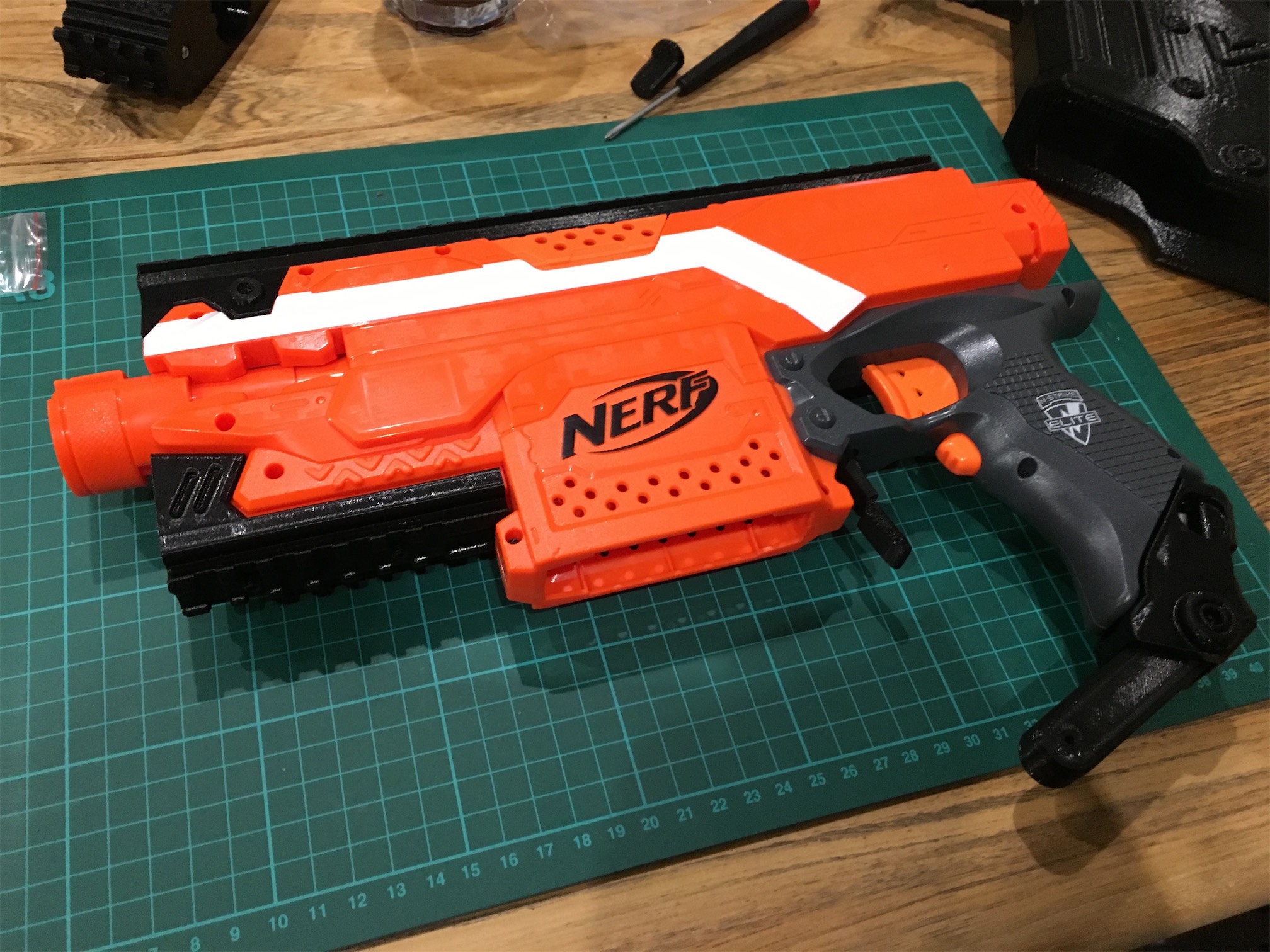
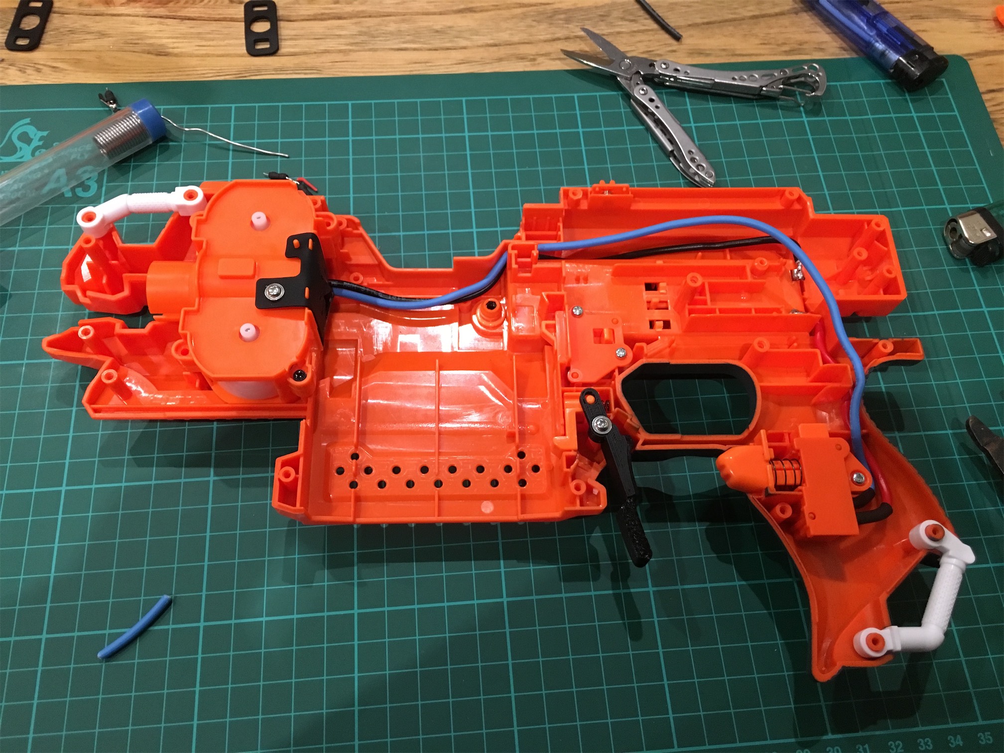
    I started off with taking the Stryfe apart to remove the locks and do a rewire.
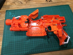
    IMG_8159

    IMG_8163

    IMG_8166

    I realised as this was my first attempt, it was going to be tricky, but it wasn’t too bad.  I made some mistakes and will be redoing this again when some more parts arrive.

    Whilst I had the stryfe apart I fitted a new 3d printed magazine release catch designed by Gavinfuzzy on reddit.  He very kindly shares the Stl files so that I could get it printed locally.  As sadly the shipping for so such a small part was astronomical otherwise.  It was my first bit of 3d printing and I discovered that there is a 3d printer manufacturer just down the road from me.  (YAY!)

    IMG_8155

    Next was to wait for more parts to arrive.  The main parcel was from YOYbuy with the Kriss Vector parts.  I also stuck some ebay orders in for Black banana magazines from Blasterparts.de as well as some motors from Blastersmiths (Also seemingly just down the road).

    Finally the parcel from China appeared and after the painful Customs bill I had the parts in my grubby mitts.

    IMG_8323

    The F10555 parts are 3d printed and are excellent quality.  I was very impressed with them.  I picked up a few worker bits as well that I would need.

    The first job was to fit the stock together.  It is adjustable so I managed to find a good size for my build.

    IMG_8324

    Next when ordering I made the first of my two mistakes.  I had ordered a separate rail cover for the bottom of the Stryfe.  This isn’t needed, but I tried it on to see how it fitted.  I also fitted the main top rail.  Both these went on really easily.IMG_8330


    Next I ran into some issues fitting the magazine cover part.  Basically the bottom rail cover was wrong.  It had rails that were much larger than the ones on the Stryfe.  Which is odd as the other rail mount fitted fine.  Either way, I had to come up with a solution, so I took the dremel and cut off enough of the rail until the bottom rail fitted ok.  A bit of a pig, but fine in the end.
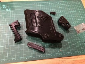
    IMG_8328

    IMG_8331


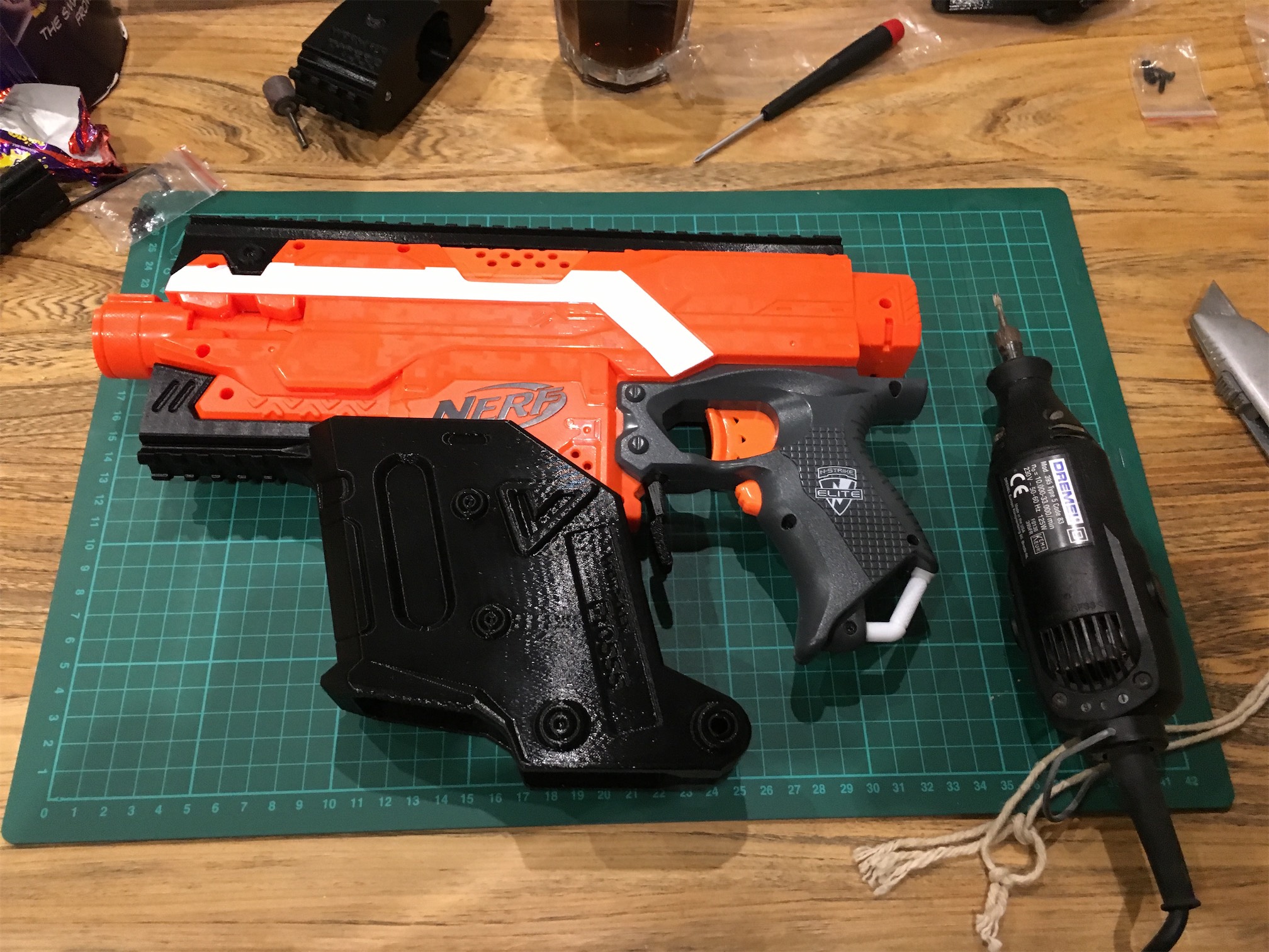
    Next I fitted the grip to the clip cover section.  It’s all really well built and thought out so this went well.  I could then fit the front cover on as well.  This uses the existing nerf barrel connection and is very quick to fit.  I put on the front grip and the flip up sights I bought.   My second mistake was discovered it.  The side inserts came with a single 10cm rail instead of two 5cm one’s so I’d have to order some replacements.  I’m not sure if this was something I ordered wrong or was sent out wrong, but not to worry.

    IMG_8333

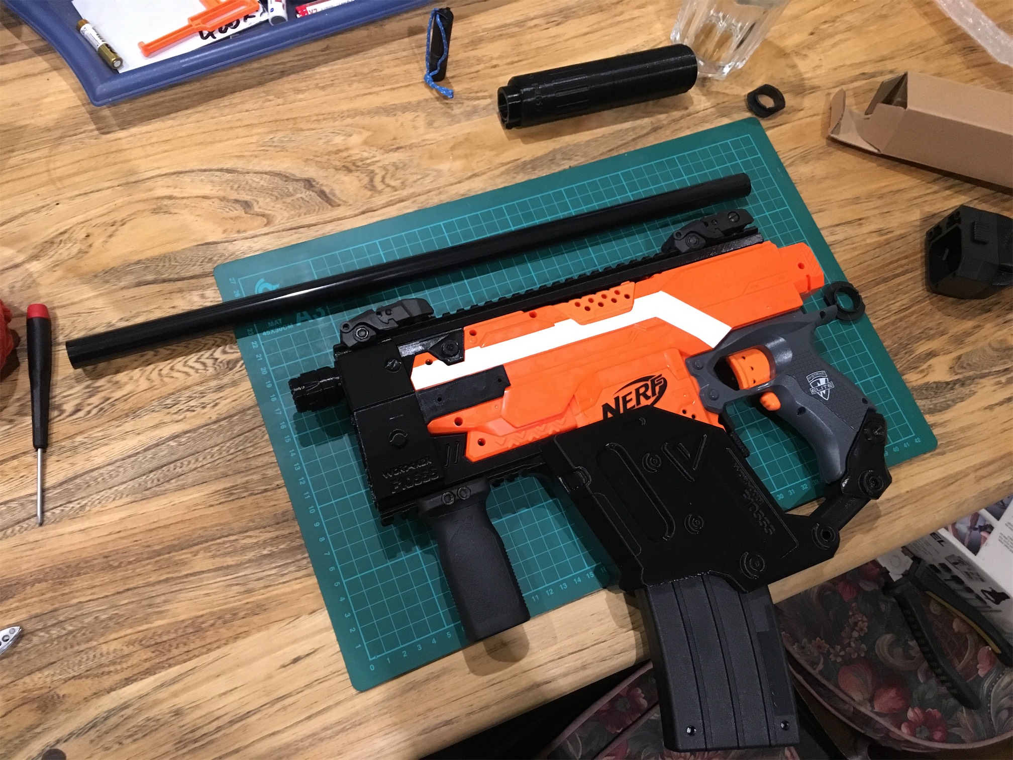
    It’s starting to look really good now.  I next needed to fit the barrel and silencer.  I made another ordering mistake here and got the longer silencer.  It’s a bit too long for my liking, but I will order a shorter one.  Cutting the barrel was fairly simple but my advice is to make sure you measure properly and make sure the barrel is really fully in the silencer….  Not that I cut wrong of course (cough!).  Good job there is a long section of it!

    IMG_8334

    IMG_8338

    Finally all the pieces were in place, and I could fire it up.

    IMG_8347


    Currently I’m running it with 2 imr’s and 2 dummies.  It fires really well with loads of noise!

    Jobs and parts left to fit are as follows:

    Worker flywheels
    Rhino Motors
    Silicon Wiring
    Side rails
    Sling mount and sling
    Sound deadening.

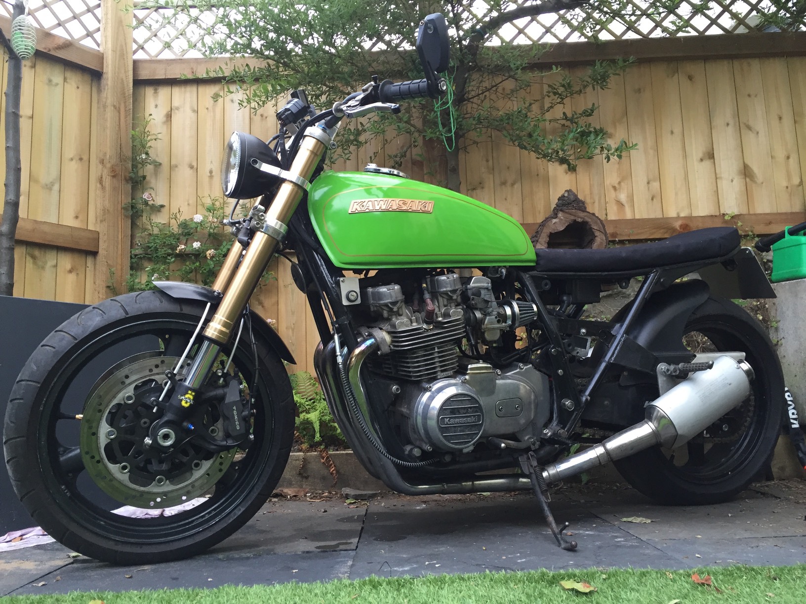
  • Picture of my KZ650 so far.

    I need to keep working at it until it’s done.  However here it is at the moment.

    IMG_6545

    IMG_6544

  • Carbs fixed but now something new

    So I promised an update. Well Tim worked his magic on the carbs and timing. He got it so the bike stopped surging at mid revs and re-jetted so that the power was actually smooth line as the revs increased. Test riding it round the lanes and it was transformed into an amazing ride.

    However as with this whole project my luck sucks, I rode in the center of town feeling very happy however on my trip the bike completely cut out with no warning. I managed to get it restarted, but the same thing happened three more times in less than a mile. I managed to get to my destination, but I was pissed off. Interestingly when I started the bike to go home it worked fine all the way home.

    Once home I checked things through and with discussions with Tim, I think there is a dodgy connection to the coils. I will be checking the wiring through and changing old dodgy connectors.

    I took a couple of pics of the shop
    My bike hiding amongst many others. So many spares in this corner.
    IMG_6929

    Some drag bikes
    IMG_6928
    Another job I did before the trip to Tim’s was to sort two things on the rear of the bike.

    1. A slow puncture
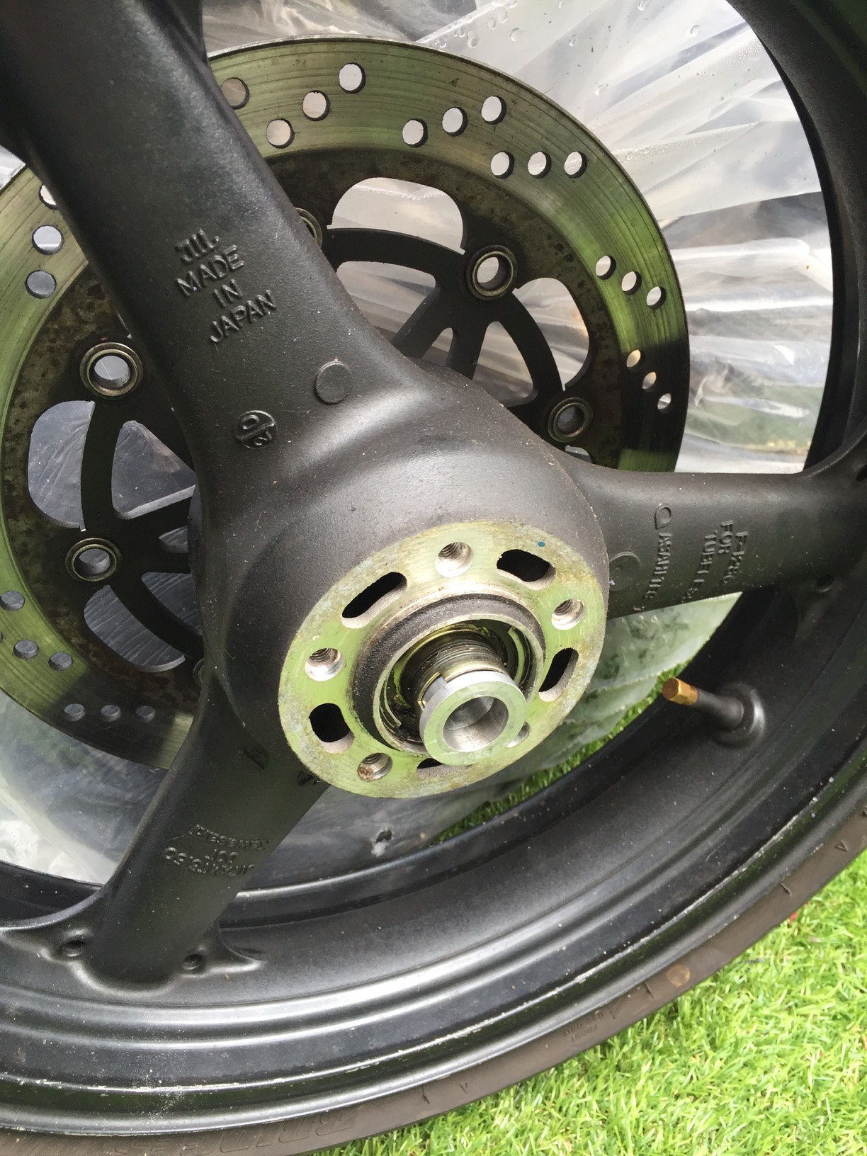
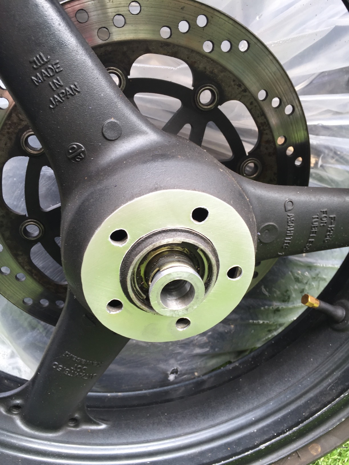
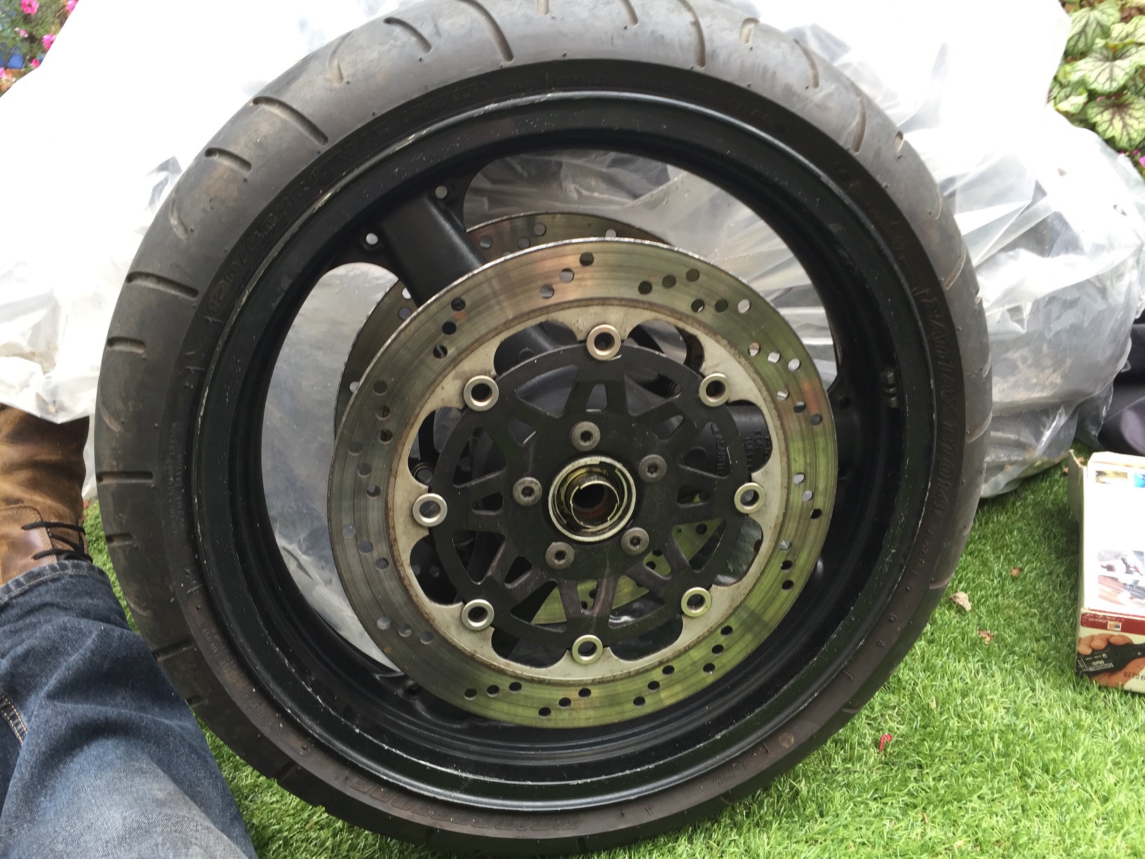
    2. Replace the rear disc.

    I managed to do both of these at the same time.

    IMG_6850

    Old disc
    IMG_6848

    New Disc
    IMG_6847

    New disc and wheel back on
    IMG_6911

    Now I’m back from holiday I can attack the wiring. I saw a camo Z650 when I was in the Lake District too.
    IMG_6968


  • Mudguard fitted & carb woes

    Quick pre MOT update and mudguard pics.

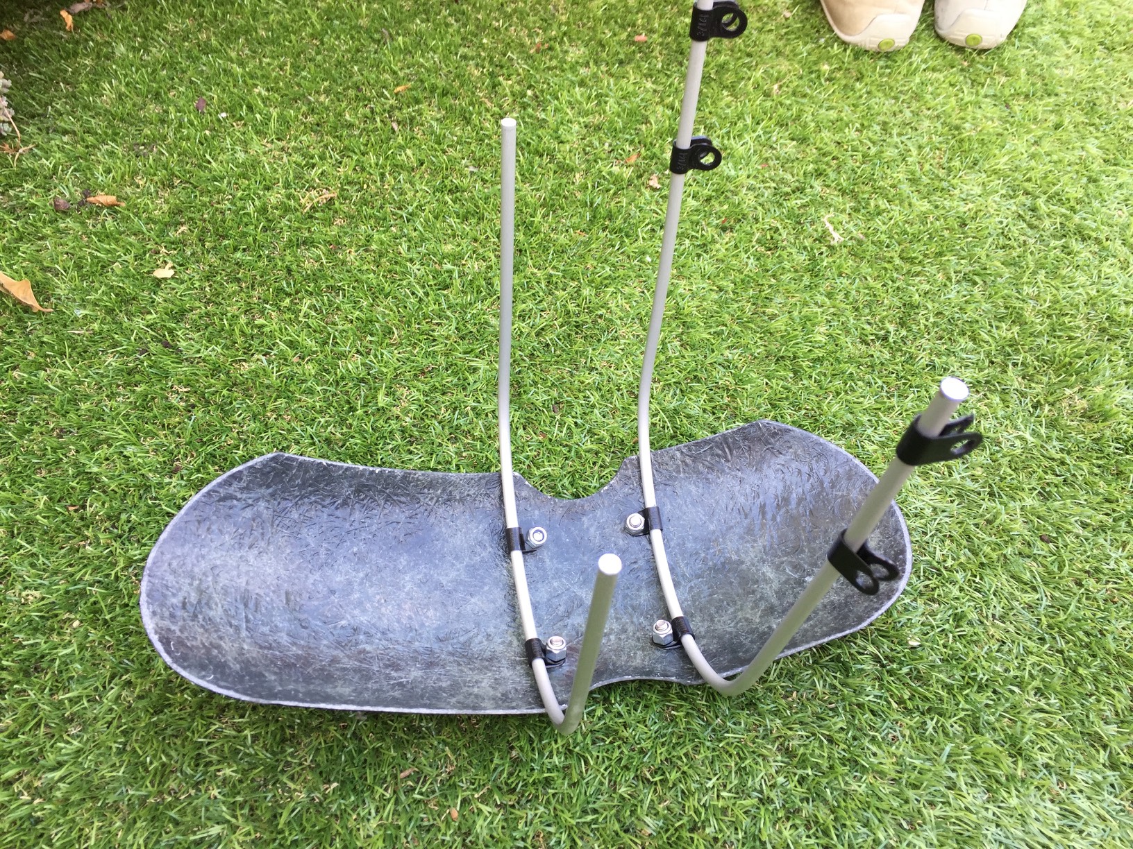
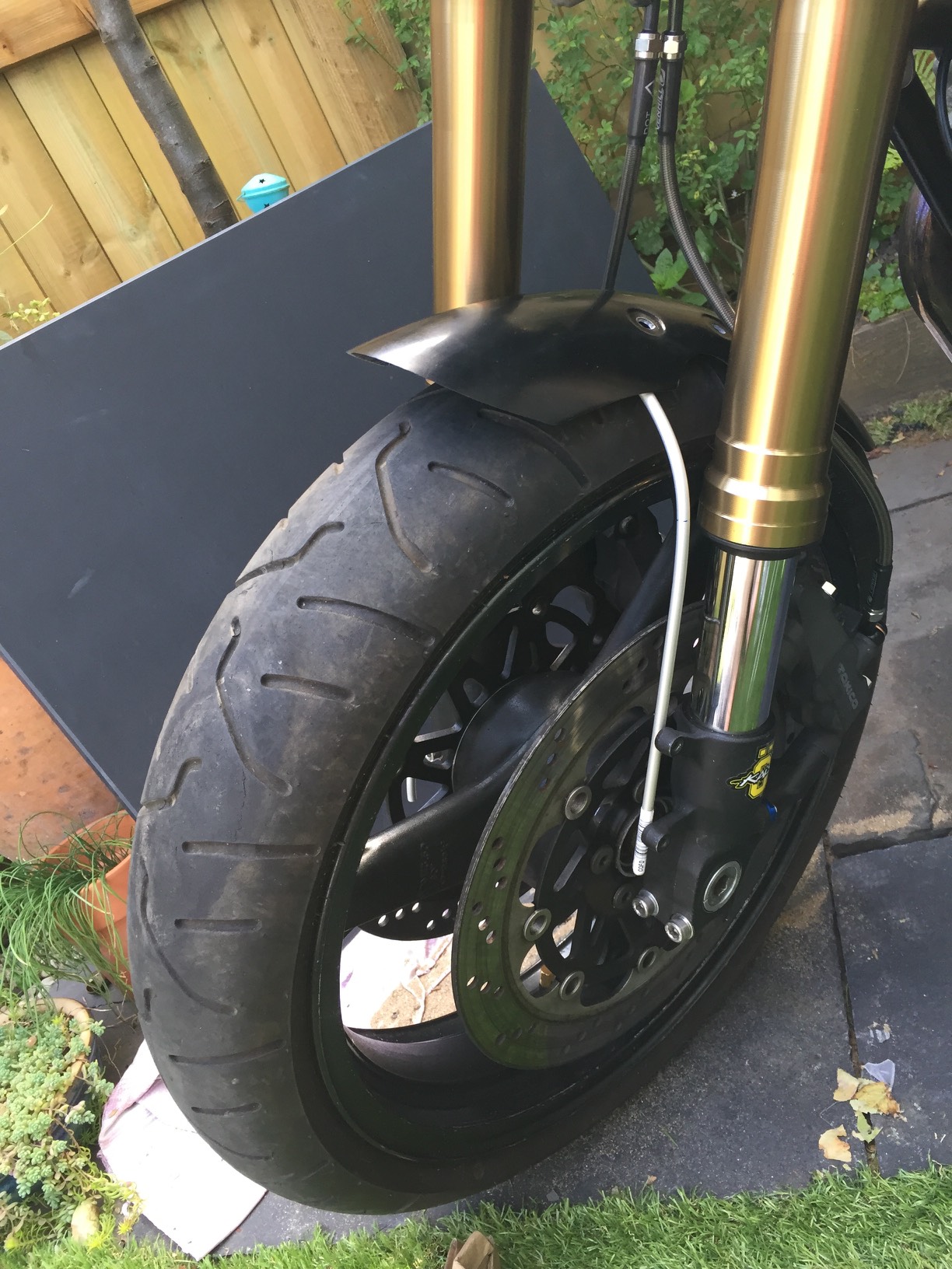
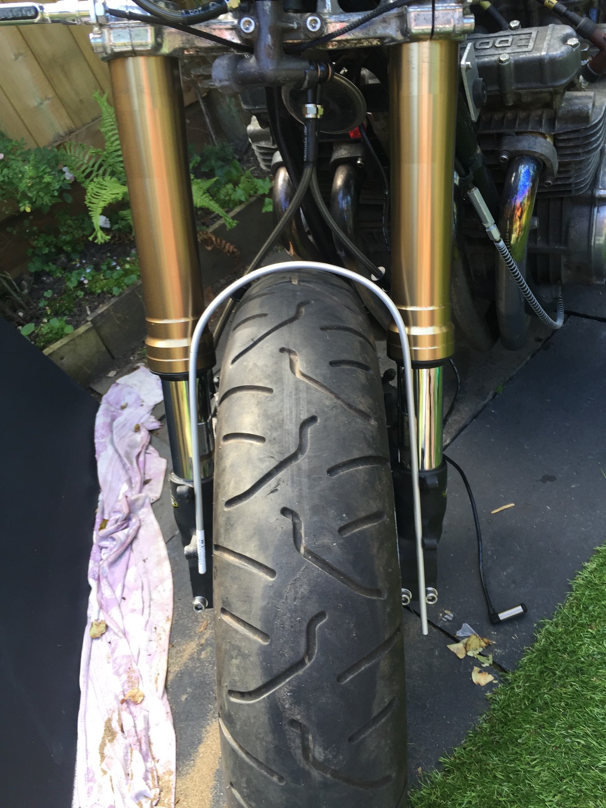
    I managed to create a mount for the triumph mudguard using aluminium pipe bent to shape and attached with P-clips. I had no idea whether it would work or not when I started. First I used the rear tire as a bending guide as it’s about the width that I needed. This gave me the front bracket which I attached to the mudguard as a test.
    IMG_6541

    IMG_6542

    That worked really well so I set about making the second bracket for the rear.

    IMG_6543

    What I had failed to think about was how to get the brackets and mudguard into place. I had hoped to leave the brackets attached to the mudguard and slide them on, but that was never going to work. So i had a very fiddly time trying to mount the brackets to the mudguard once they were in place. With a lot of swearing and dropping nuts I got there.

    IMG_6546

    IMG_6548

    IMG_6549

    I am so delighted in how it turned out. I never expected it to work so well.

    Next it was time to refuel the tank and fire it up. This is where the headache started. The bike started ok, but sounded odd, I realised that it was pissing fuel out from somewhere. Not good. I also realised that one of the exhaust headers was cold not hot. Also not good.

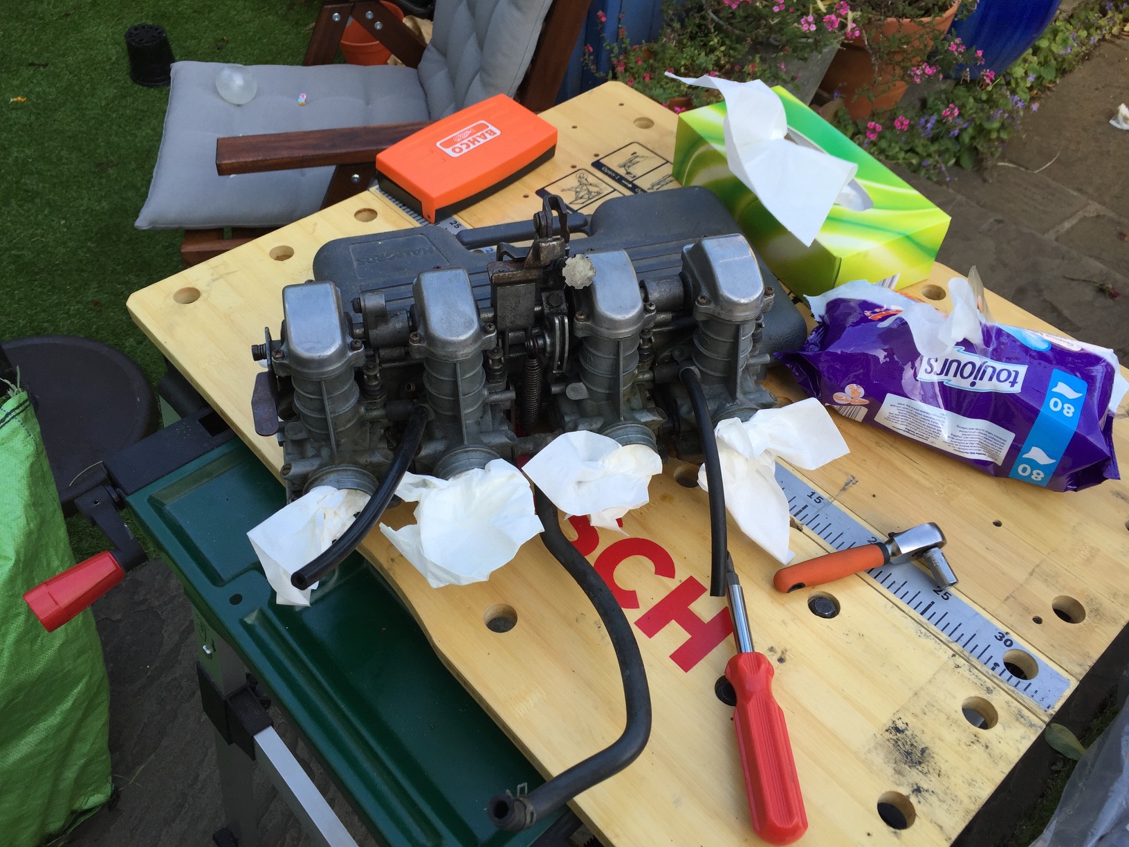
    I rapidly realised that there was probably a carb issue. I’ve avoided touching these so far as I don’t want to cause more issues than I fix, but needs must. I took them off the bike which was much easier than I was expecting. Thankfully I didn’t need to remove the tank either.
    IMG_6574

    IMG_6575

    I found some blockages in the carb that I thought was the problem and managed to clean them out. I’ve just put them back in and it seems to have sorted the issue out. Certainly it sounds better and is no longer pissing out fuel which is nice!

    A job for this winter is a proper carb clean inside and out.

  • Brakes and other jobs

    I’m so close the end of this….

    I’ve made a chunk of progress though it doesn’t all show. The main jobs left to do from last time was sorting the wheel placement and fitment. I then also need to fit the brake calipers.

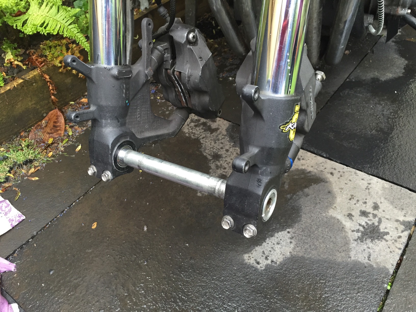
    1. Front axle
    I had the axle machined down to the correct length. This meant I could finally test fit the wheel and get the correct spacings

    IMG_6476

    IMG_6478

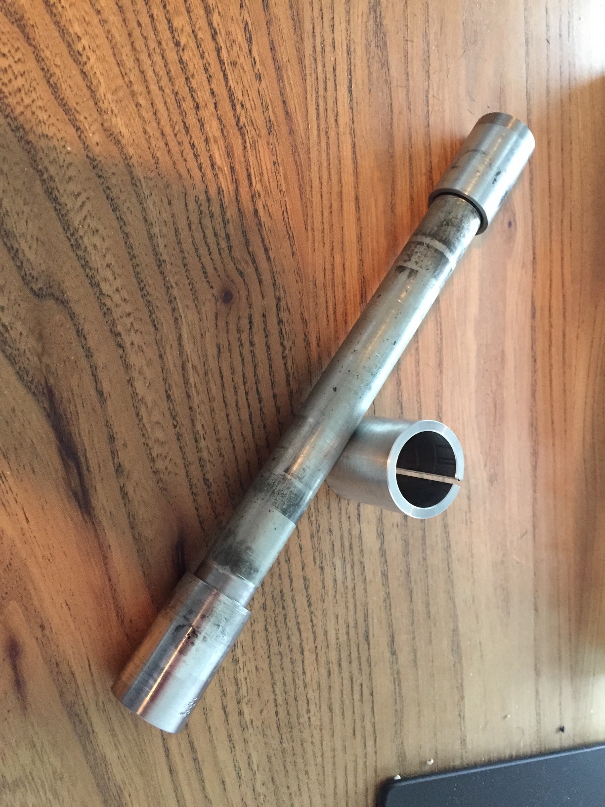
    2. Front axle spacers.
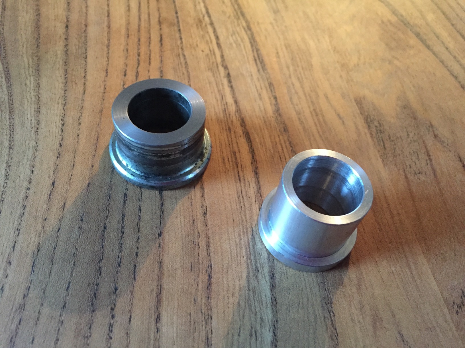
    The local engineering shop also made up two more spacers for me, once I had worked out what size wheel spacers I needed. I got them to machine down the existing spacer as it was quicker for them. They then created the second one.

    IMG_6496

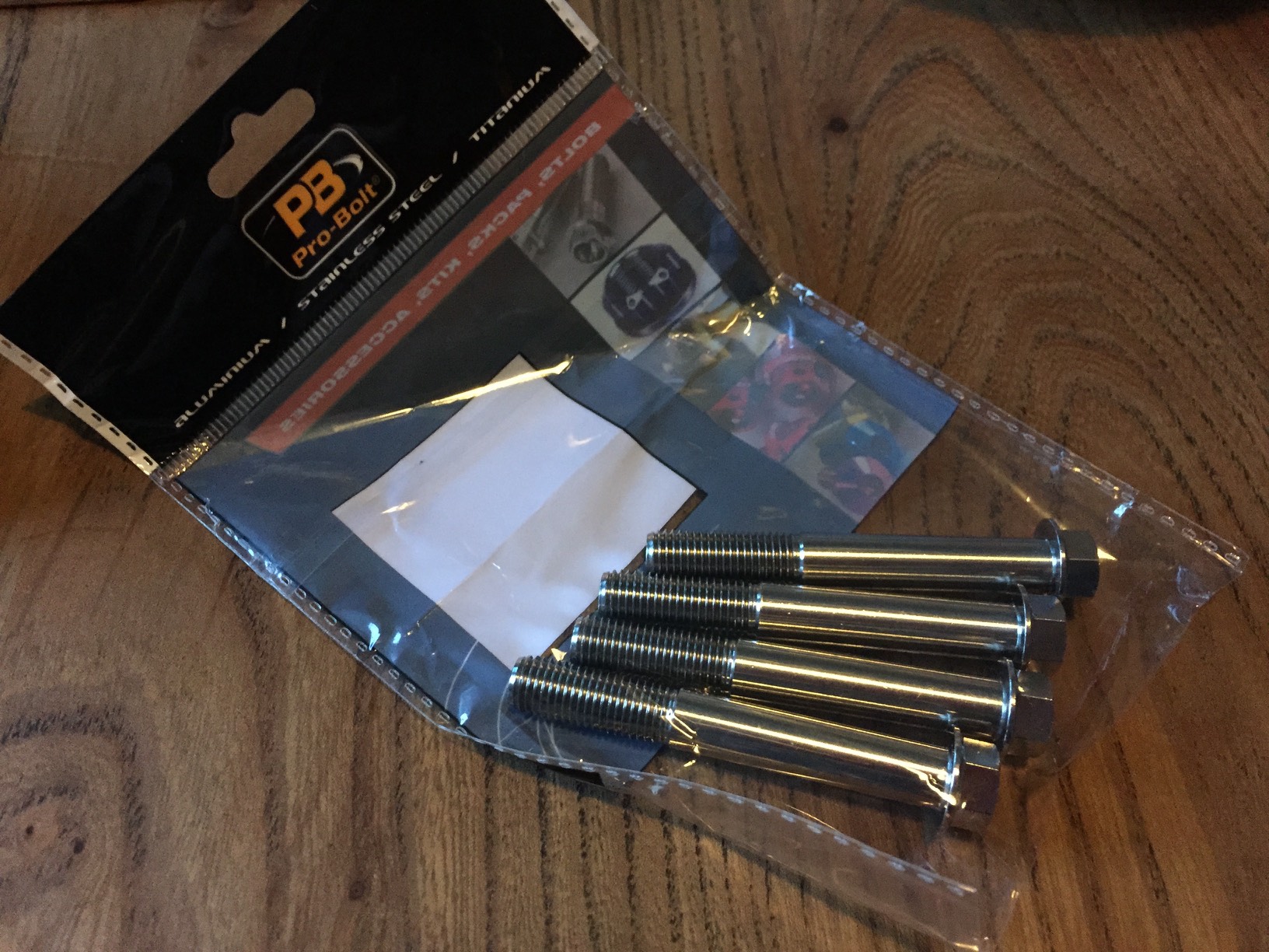
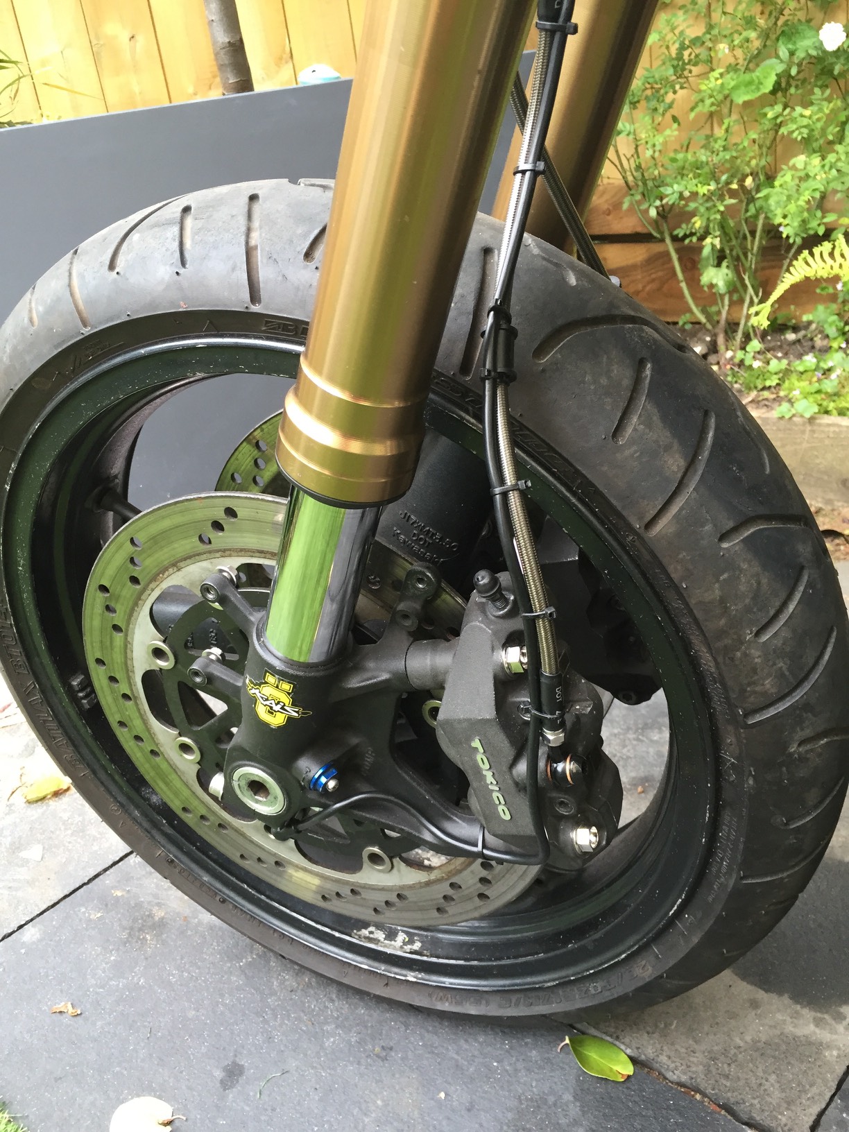
    3. I picked up some new caliper bolts as the calipers didn’t come with any. This allowed me to fit the calipers and see if it would even work!

    IMG_6468

    IMG_6473

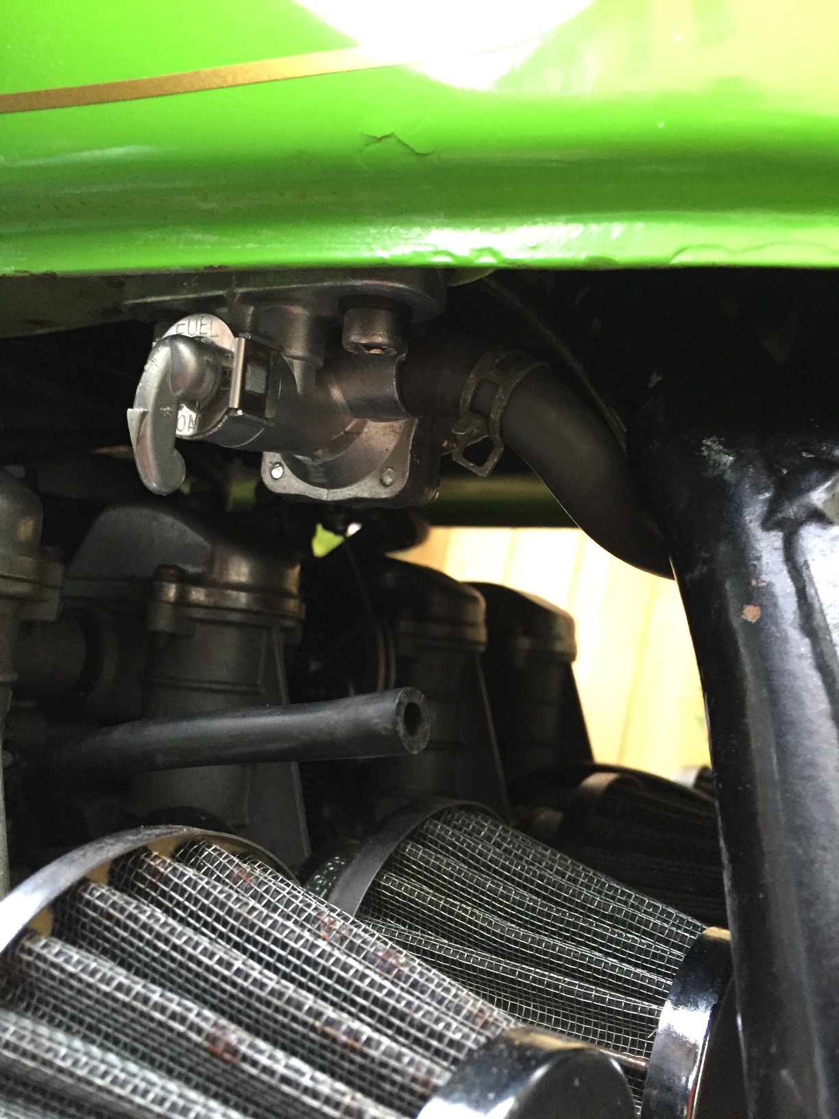
    4. The original petcock was on it’s way out so I tried to find a suitable replacement. After much research it appeared a Suzuki GS450 one would work, so I ordered one. It turns out it will fit the tank perfectly, but you cannot get it the tank back on the bike! In then end I just put the petcock in with the tank in place. This creates future headaches when removing the tank, but it will have to do.

    IMG_6490

    5. Disc spacers.
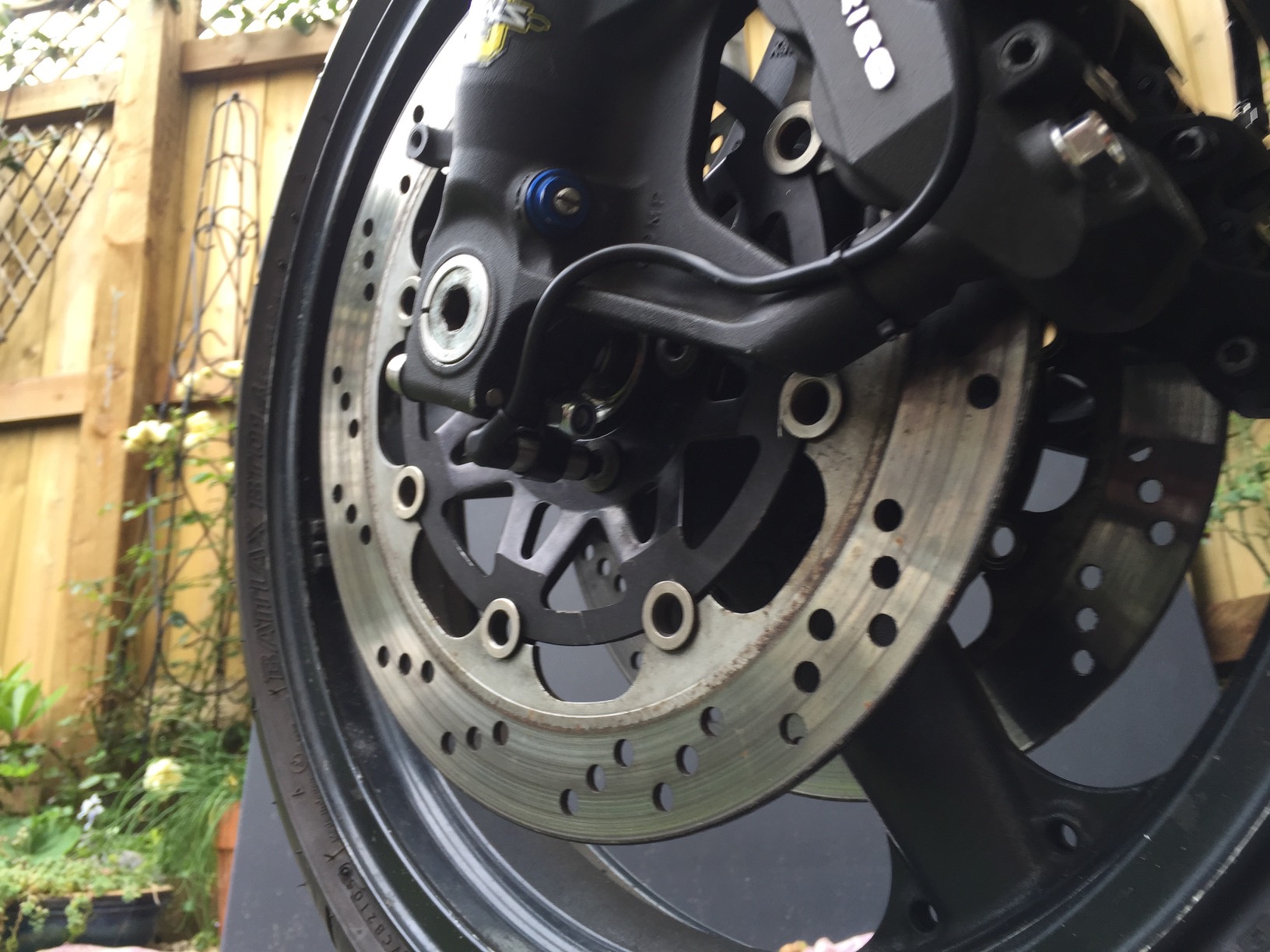
    With the axle and wheel spacers in place I could finally work out what to do with the discs. As they were touching one side of the brake pads on each caliper. It was around 1.5mm out. I tried to find some suitable disc spacers, but couldn’t find any. In the end I just made my own. In the end they worked perfectly and didn’t take me too long to make.

    IMG_6504

    IMG_6505

    IMG_6506

    6. Brake hoses
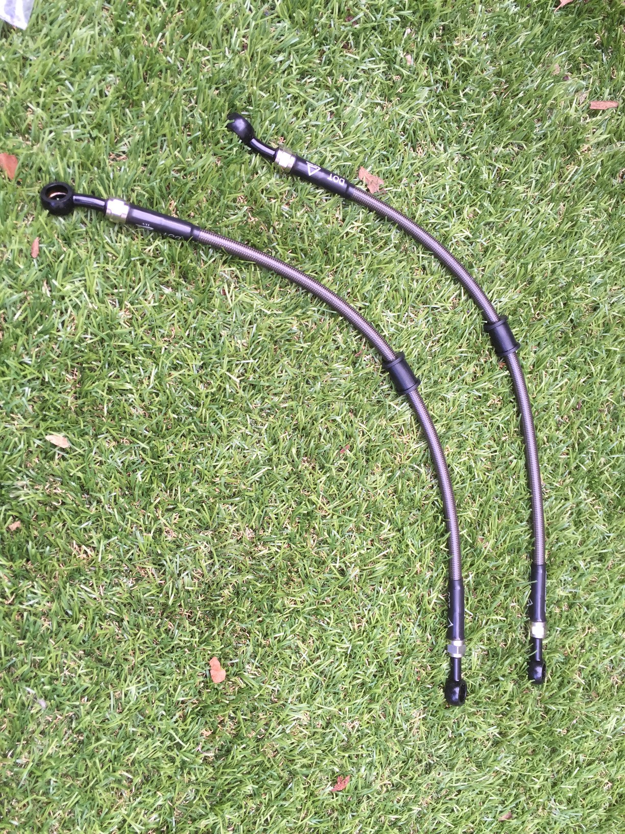
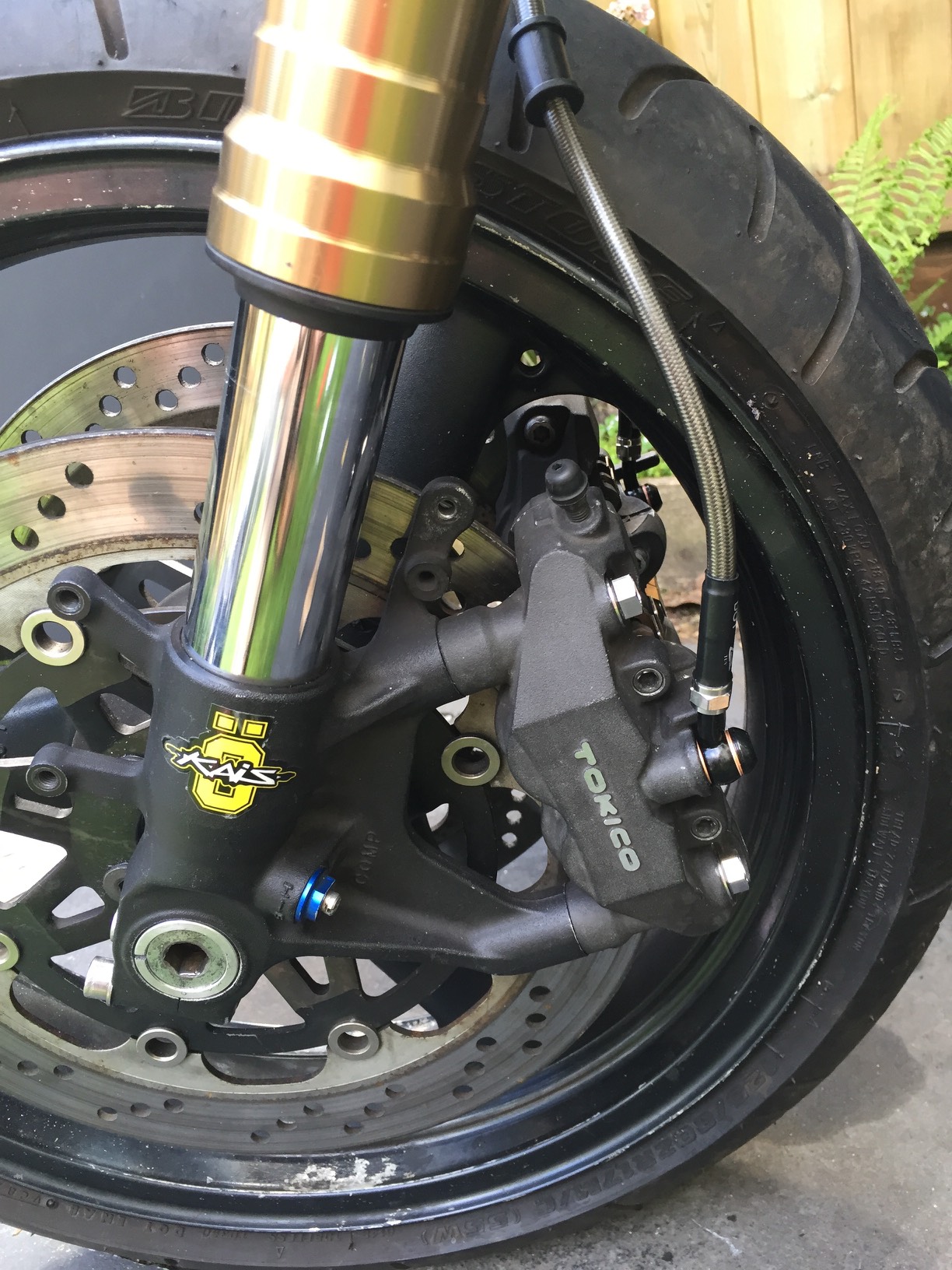
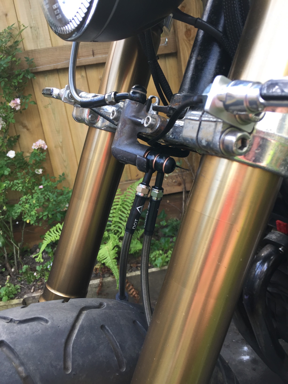
    With the fitment of the brakes I could finally get the brake caliper hoses ordered. I went with some nice Venhill ones like I had used before.
    IMG_6511

    IMG_6512

    IMG_6513

    7. Mudguard mounts
    I’ve not finished this yet, but after various attempts I think I’ve got the design sorted. It uses some round 6mm aluminium, I bent it to shape around the rear tire to get the perfect bend. I tried to hammer out mountings, but found it far to hard to be perfect. So now I am using some little brackets that I’m waiting to arrive. The pics give you an idea where it’s heading.
    IMG_6518

    IMG_6517

    IMG_6516

    8. Speed sensor
    The final job I’ve done was to find a place to mount the new magnetic speed sensor. In the end I’ve used a longer cinch bolt on the bottom or the forks. On the extra end section I’ve mounted the Koso speed sensor using the p clip to get it in the perfect place, I then routed the cable using the brake hose as a path for neatness.

    IMG_6540

    IMG_6539

  • GSXR 600 Forks fitted

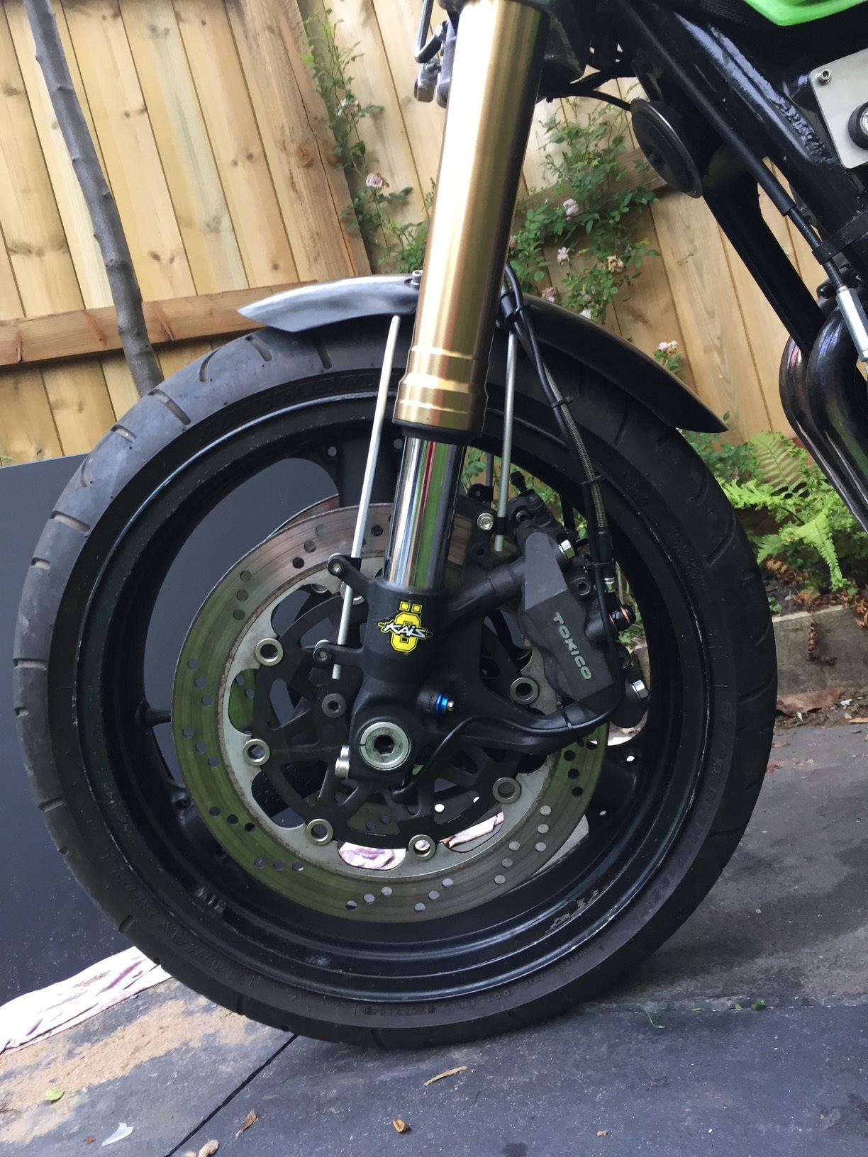
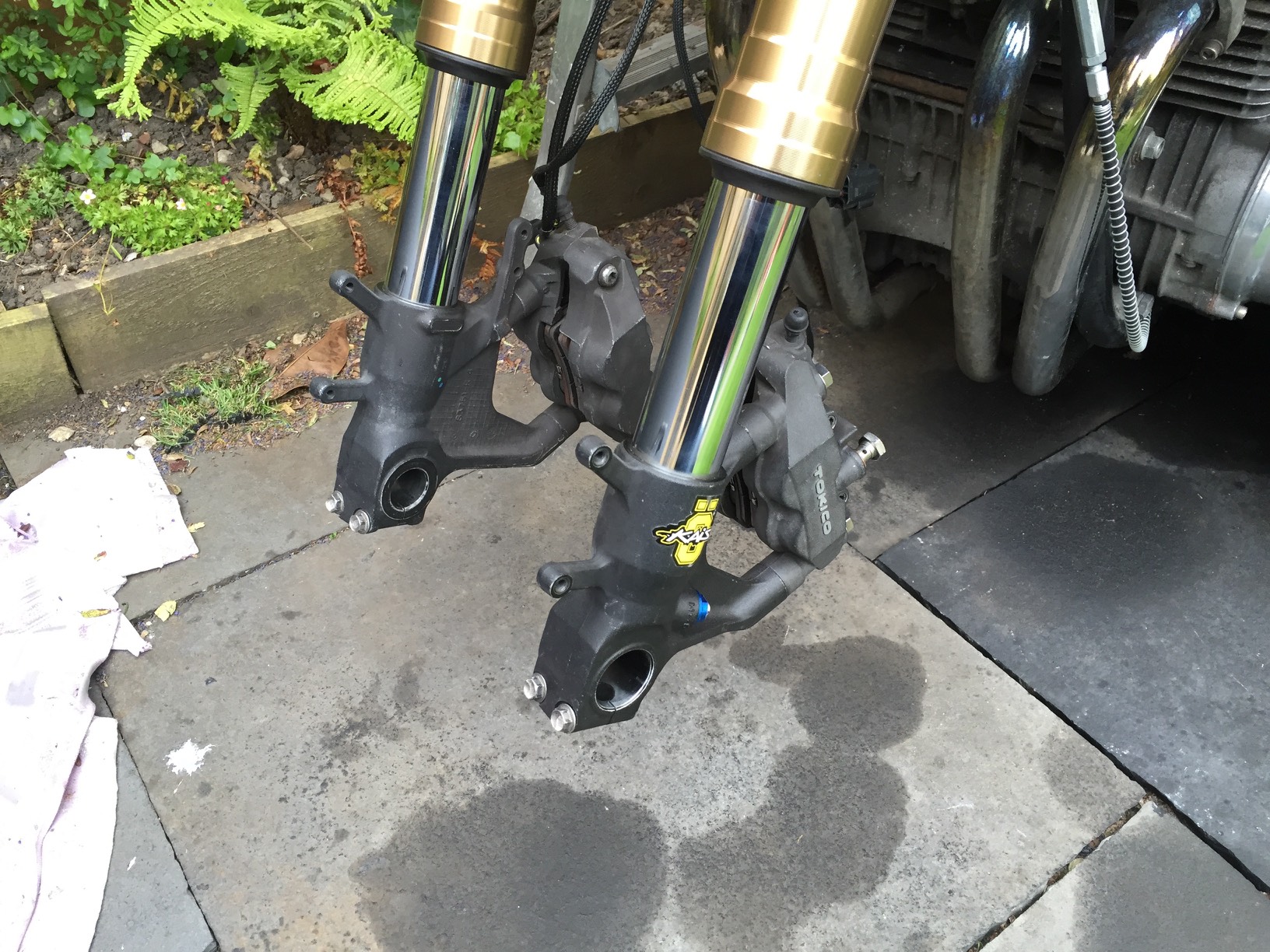
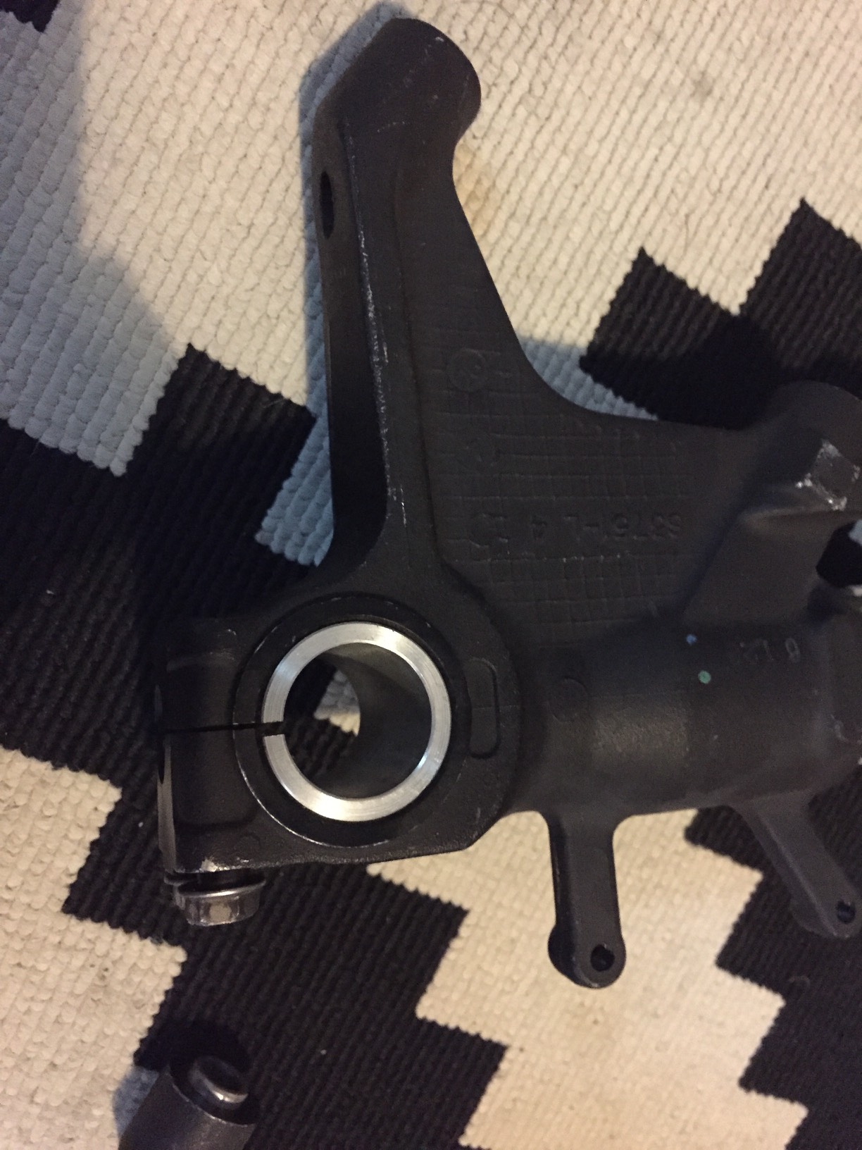
    Well more forward progress towards the getting it back on the road. I had both the bottom yokes and front axle machined to fit the new GSXR 600 forks. They also made up a spacer to fit the larger axle hole in the forks.

    IMG_6435

    IMG_6437

    IMG_6436

    I could then try my first test fit of the forks to see if they would work

    IMG_6440

    I then tried to fit the brakes and wheel and hit a major issue. The brakes wouldn’t go on! After 10mins of panic I realised I got the forks on back to front! What a bloody idiot. Anyway I swap the forks round.

    IMG_6443

    The axle is correct in the diameter, but too long, but the wheel fits in place and the axle works! I have taken it back to the machinist to get it down to the correct length.

    I have a few more issues to now over come.

    1. The original speed sensor will not fit so that has to go.
    2. I will need axle spacers or the correct size to make sure the wheel stays in place.
    3. Both front discs touch one side of the pads

    These are relatively easy to over come.

    1. The Koso DB-01R I have has a magnet sensor option which I can pick up locally tomorrow.
    2. These will be hard to measure as the wheels are not identical either side, but once measured I can get some knocked up.
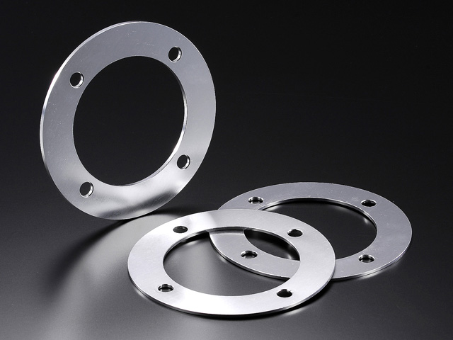
    3. This is harder, my first reaction was to think about some washers behind the disc, but that seems like a terrible idea. So what I will do is make some spacers out of sheet alumnium that cover the whole of the contact patch. I’m waiting for the axle spacers and brake bolts to turn up before I start these. I’m thinking of something like the picture below.
    39347

    I have also broken two things when putting everything back in place. I broke the starter button cable which is very annoying. I also found the mounting bracket for the Koso speedo was snapped off. I’ve managed to glue that back in place.

    I should have the axle back later this week so I can get some more work done this weekend.

  • Old forks new Forks

    Well as seems to be the case with this project. It’s been two steps forward one step backwards. I’m losing the will with it at the moment.

    When last I did an update I was awaiting tools so that I could remove the front axle and therefore the front forks. I managed to do this in the end and took them into the garage to have the seals redone. However after discussing it with them, they noticed some rather bad pitting on the inside of the forks hidden from view. They recommended that they would need to be rechromed sometime soon. As a short term solution to get me on the road I asked them to replace the seals anyway and I would look at more long term solutions.

    However they simply couldn’t get the forks to come apart, they tried everything they could including using a blow torch to heat them up. So we had to abandon them. I have to give the garage thumbs up as they must of spent hours on them, but didn’t charge me a single penny.

    That gave me a big headache, I saw little point in spending a fortune on similar ZXR400 forks as they would also be nearly 20years old and need work soon. I headed to the web to see if I could find a suitable alternative option.

    What I was hoping for was some forks of the same diameter as the ZXR400’s but newer and more modern. This proved to be fruitless. I could just do a whole front end swap, but I wanted to not spend a small fortune on this! Eventually I settled on some forks that I think will work, I had to do a ton of research and all kinds of bikes to find out what would be best. I even had to use a spreadsheet :sick:

    The ZXR400 forks are the following dimensions
    Length 745mm
    Top Yoke Diameter 50mm
    Bottom Yoke Diameter 52mm
    Standard calipers
    310mm Discs

    The closest match I could find we GSXR 600 K6 forks, they match for everything apart from the brakes, bottom yoke, mudguard and axle….. Groan :sick:

    Queue some expensive ebaying
    IMG_6387

    IMG_6388

    Next I have to get the old forks back of the bike as I put them back on so I could use the ladder!

    IMG_6289

    I then set about removing the yokes as well. I thought it would be a nightmare, but it wasn’t too bad

    IMG_6413

    IMG_6414

    Next week I will be taking the axle in to be machined and a spacer created. As it’s a pretty close match. The yokes will be machined out from 52mm to 53mm. The light brackets will also need to be changed, but I’ve already sorted them out with some small rubber pieces to act as spacers.

    I also had to find a new mudguard which was particular annoying as I’ve only just had this one made for me! I wanted something more similar to this bikes one

    cx500-cafe-racer-1

    I managed to find a small triumph mudguard. I will need to make a custom mount for it

    IMG_6412

    So there we go, another depressing update, but I can see some blue sky in the future at least now.